Last month, I posted some pictures of my 9-inch differential section as I was tidying it up for a rebuild. I was very lucky to have good and rare 9-inch differential “cores” to work with even if getting all the correct pieces in place was a bit more effort. But a little due diligence resulted in acquiring top-shelf parts to perform the rebuild with confidence and a small measure of pride mixed in.
In the middle of working on the rear suspension, I finally started putting the differential (a.k.a., Pig, Hogshead, third-member, diff, chunk, carrier, etc., etc.) back together with brandy-new shiny parts. On the menu for this center section is a new 3.89 ring and pinion from Motive Gear, new Timken bearings everywhere, a Raetech solid pinion shim kit, an Eaton Detroit Locker (a.k.a. “soft locker”) differential, all stuffed in my original nodular iron case and finished off with a genuine Daytona pinion support. This is just about as bulletproof as any factory 9-inch ever got.
Now, I won’t go through the details of a complete 9-inch rebuild as there are many good resources for that information already, but I will touch on a few things that I did and/or learned along the way. In fact, for anyone contemplating a 9-inch rebuild, I would recommend checking out the video tutorials available from Ken Collins at Bad Shoe Productions. Ken is a talented and very experienced Ford Master Technician and he shares his vast knowledge in affordable, easy-to-follow educational videos. Look him up and tell him I sent you. You won’t be sorry!
In the meantime, I am very happy with how the rear axle assembly is shaping up and I enjoy the feeling of confidence that I have knowing I spared no effort in getting the “right stuff” in place.
 |
| There's quite a bit of work involved in proper setup of the pinion & support, particularly in getting pinion bearing preload just right. The important lesson I learned in setting up the solid pinion spacers on 9-inch differentials is to bring it up to full torque on the pinion nut to check the preload. Some spacer manufacturers recommend a much lower (approx. 130 ft/lb) nut torque and this simply does not work. I used 200 ft/lbs on the pinion nut and the preload worked out perfectly. |
 |
| Ring gear bolt torque is another detail that you get wildly different specs on as well as opinions on the use of thread lock compound (a.k.a. Loctite). My experience has been to always trust the factory service specifications for ring gear bolt torque and use no Loctite on these fasteners. Why? Because torquing ring gear bolts is a relatively slow process that should be done in steps until final torque is achieved. Believe it or not, Loctite will begin to harden within seconds of placing a bolt in a hole and this is not conducive to accurate torquing when the process lasts more than a few seconds. Besides, a properly torqued (stretched) bolt should not require thread lock in most cases. |
 |
| When dealing with several torqued fasteners, it is difficult at best to keep track of every bolt that has been torqued. My favorite way to help me ensure I don't miss a bolt is to apply a paint mark to the bolt head and mating surface immediately after final torque. This also works very well during maintenance inspections to ensure none of the torqued fasteners have moved. |
 |
| Most ring and pinion sets are shipped with a rust preventative coating on the gears. This coating needs to be removed before installation to prevent any problems with gumming and to make sure you get accurate gear contact pattern representations when doing your final gear mesh checks using gear marking compound. I like to use lacquer thinner to remove all of these oils before installing the ring and pinion gears. |
 |
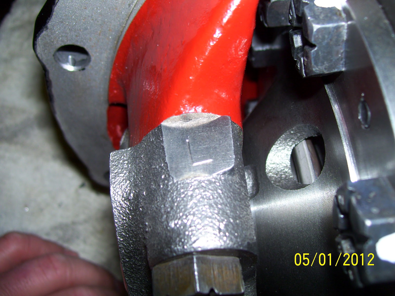
| If you happen to be the first person to rebuild a particular 9-inch differential, chances are, the main caps will not be marked as to their proper location in the case. Since these caps are machined to match the case, they cannot be mixed up (just like crankshaft main caps in an engine). Therefore, it's a good idea to mark the caps before removing them to ensure they are returned to their proper location during rebuild. In this shot, you can see this cap is marked with a large "L" to indicate this is the LEFT (or driver's side) main cap. |
 |
| In similar fashion to the above photo, this cap is marked with a large "R" to indicate this is the RIGHT (or passenger's side) main cap. |
 |
| Proper 9-inch case setup is not [possible without some accurate means of turning the bearing adjusters. I made this simple pin spanner wrench out of some 1/4" flat stock and 5/16" rod and welded up two wrenches in a few minutes. You could easily make something similar using a pair of 5/16" bolts if welding capabilities are unavailable. |
 |
| Backlash settings are one area where the gear manufacturers specs must be followed to the letter. Depending on the gear machining and finishing processes used by the manufacturer, the backlash targets can vary by several thousandths of an inch. In my case, I chose a gear set from Motive Gear, who laps both the drive and coast faces of their gears during final manufacture. This is rather unique and allows backlash targets to run slightly tighter than many factory and aftermarket gears. My average backlash (measured at three locations around the gear) was set at 0.010". |
 |
While many gear manufacturers reference a measured pinion depth, it is rare that using this dimension alone will create the ideal pinion depth. I have found the best option is to start with the pinion shim that came with the differential housing from the factory (if possible). Nine times out of ten, this will nail the pinion depth on the nose. Ford always references the "master case depth" specification in their pinion shim establishment, so using the same thickness pinion shim as installed from the factory is always the best place to start.
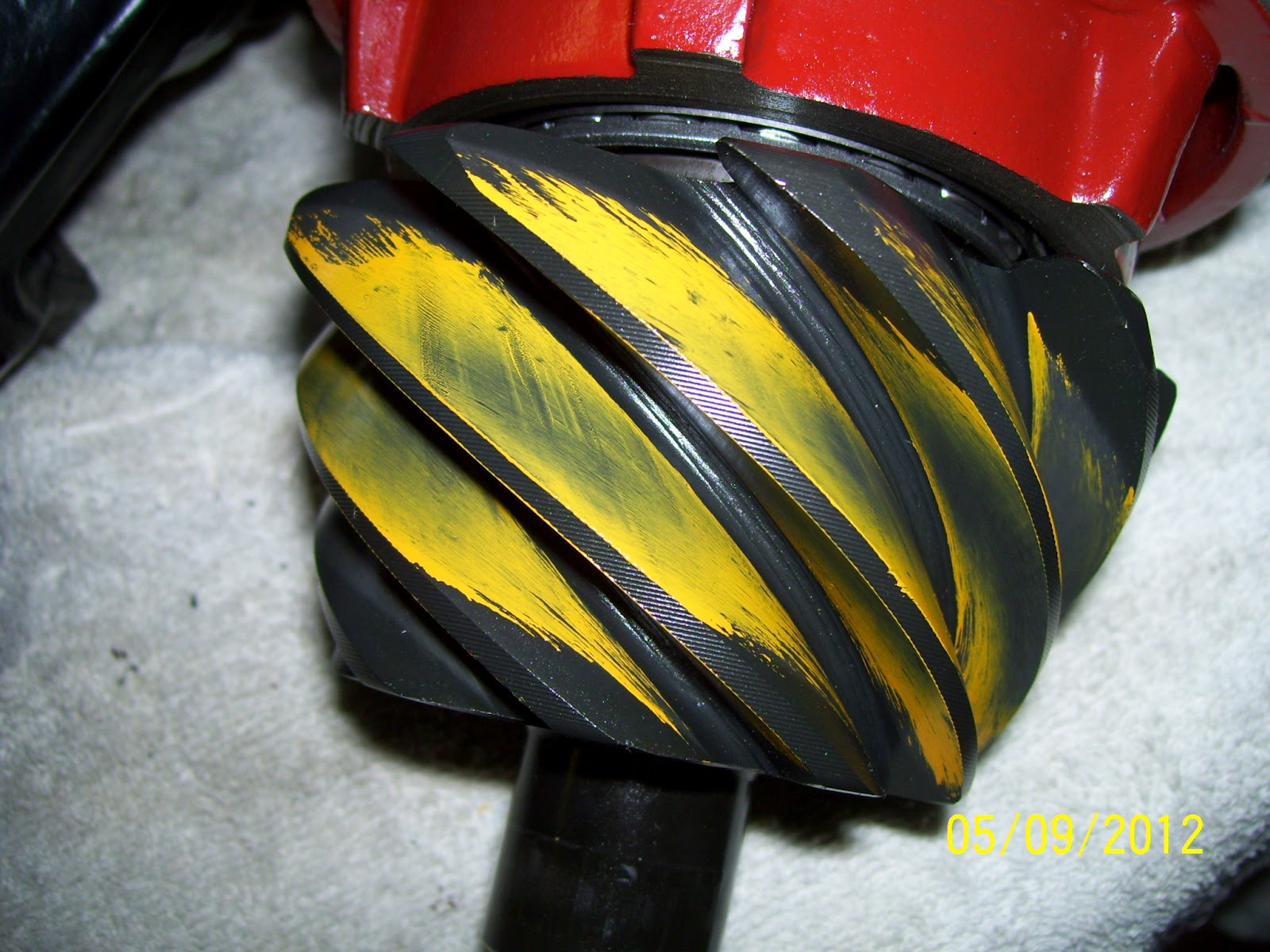
In this shot, you can clearly see an almost perfect gear pattern on the drive face of the gear. The contact is perfectly centered from the toe to the heel of the tooth as well as from the root to the tip. It doesn't get much better! |
 |
| On the coast face of the gear, the pattern is again almost perfect. The contact is biased slightly toward the toe (e.g., the inner diameter) of the gear tooth and is well centered from root to tip. |
 |
| While not generally something that is referenced in gear pattern charts, the pinion contact should also be well centered over the entire tooth face, similar to the ring gear. Here is the coast side faces showing a nicely centered pattern. |
 |
| And here is the drive side faces showing excellent contact position as well. |