Friday, November 5, 2010

Prep work leading up to engine bay sand blasting & priming

The latest round of work has been a mixed bag of various things in preparation for sand blasting and priming the entire engine bay (firewall forward).  I apologize if the following pictures look a little "disconnected" but there really is method to my madness.......at least that's what I keep telling myself.

Anyway, the series starts will the first official job using the rotisserie:  the entire undercarriage of the car was thoroughly pressure washed to rid the car of  as much of the caked mud, grease, loose rust, etc. that lived on it's belly all these years.  Once all the washing was done, I was absolutely stunned at the volume of crap that was once stuck to the car!

The second phase was surgically removing the scabbed-on weld patch on the driver's side frame rail where the power steering bracket was ripped from the rail and a "repair" was slobber-welded in place.  After  a few tedious hours with all manner of air tools, the patch was removed, only to reveal some hidden cracks and broken parts inside (as expected).  I carefully cut away the damaged metal in preparation for a patch to be carefully fitted in place of the damaged material.  I also had to pull a small crease in the rail to get it as level with the other surfaces as possible.  For this job, I pulled out my trusty draw-pin welder and pulled the crease with a series of welded draw-pins.  Once this was done, I cut the pins off and ground them smooth, leaving no evidence that such work was ever required.  I plan to thoroughly sand blast the area to remove the surface rust before any further patchwork is done.

Third, I was able to identify three additional cracks in the suspension pickup points that required repair.  I used the same technique I used to repair the crack in the shock tower and all repairs will be invisible once they are primed and painted.

Next, I spent several hours touching up the sport welds forward of the firewall.  I don't like the spot welds that snag you every time you work on the car and vowed to make sure I smoothed every one of them as part of the restoration.  The shock towers in particular seemed to be one of the worst areas for this.......but not anymore!

And finally, THE BIG ENCHILADA!  As an unexpected gift, my uncle "sponsored" a brand new cowl panel assembly, which arrived in good order via the trust UPS guy.  At first blush, this looks like a really nicely made piece.  Like much of the other restoration sheet metal parts available for the 69-70 body Mustang, this part is made by Dynacorn.  This will be a pretty major undertaking that I plan to get accomplished over the next 2-3 months while the cold weather socks us in here in southeast Michigan.  Exciting stuff!

The rotisserie allowed me to pressure wash the bottom of the car very well.  The amount of crap that came off the chassis was unbelievable!

Bottom actually came out pretty clean!

After the washing, an interesting little detail was revealed.  Can you guess what it is?  Answer:  Not much red oxide primer and lots of blue paint.  Seems the car was perhaps repainted at some point in it's life.

Letting the body drip-dry after a bath......

This is the dreaded frame path after delicately cutting it away from the rail.  You can see the slobber weld beads still on the frame.

Here, I have cut away the damaged frame material and you can see how the frame "patch" is no longer part of the equation.


Another view of the frame with the damaged material removed.

The P/S bracket damaged the frame when the lower section of the frame rail ripped out and left a fairly significant crease in the frame that can be seen just to the left of the mounting hole in the image above.  Also, you can barely make out the crack through the mounting hole (running vertically through the hole in this picture) that required welding as well.

This nifty tool welds steel pins to the surface of the metal and allows the use of a special slide hammer to pull dents without the need to drill holes all over the place.  This tool has proven to be worth its weight in gold and I highly recommend one if you ever decide to tackle a restoration like this.

In this picture, I have a pin welded to the crease, ready for the slide hammer to be attached and the pull to begin.  It took about 6 pins to pull the crease, but the end result will require only a thin skim of filler to be undetectable.


This image along with the following two show small stress cracks I was able to identify with the car inverted on the rotisserie.  These cranks were virtually invisible while on my back under the car during previous inspections.

I need to straighten this flange a bit as well......


The cracks were excavated with a rotary tool to allow good weld penetration, welded up and finish-ground.

Every spot weld forward of the firewall prone to snagging flesh was dusted with the angle grinder to remove any nasty burs.  I also finished all of the other spot welds left over from the radiator support installation at the same time.

A nice, new, rust free cowl panel courtesy of my uncle!  Can't possibly thank him enough and can't beat support like that!

The next time you see this cowl, it will be in the process of being installed in the car!  Winter project on the way......

Monday, November 1, 2010

Finished rotisserie!

Finished the rotisserie last night and updated the October 28th blog entry to keep everything in one spot.  The thing works amazingly well and will definitely make many aspects of the restoration considerably easier.

The next step will be to power wash all of the South Texas mud off the bottom of the car along with all of the loose debris that seems to come from everywhere.  During the first roll test, it sounded like a Volkswagen hit the garage floor based on all the sh*t that fell out of the car (seam sealer chunks, rust flakes from the floors, sand, rocks, leaves, rat turds, ancient bolts/nuts, screws, unidentified plastic objects (UPO's), a pencil, a nickle, etc, etc.).

Now to decide if I want to replace the floor and cowl panels while on the rotisserie or if that would be better done on the ground.  Gotta think about that one.........

Thursday, October 28, 2010

Rotisserie

Pretty early on, I knew I wanted to get the body up in a rotisserie to effectively execute the restoration work on the bottom of the car.  For as much work that has to happen below the belt line on a project like this, being able to flip the car over and work while standing up is a damn sight better than laying on your back on a cold, hard concrete garage floor.

I looked at many commercially available rotisseries on the market and didn't really like any of the units I found.  Couple that with a price tag that I felt was outrageous, and it wasn't too hard to justify building my own.

After scouring the web for several weeks collecting ideas, I found I liked the unit built by a fellow who chronicled his build here:  http://www.harwoodperformance.bizland.com/1941buick/Editorial_20.htm 

While not exactly right for what I wanted in a rotisserie, it certainly provided an excellent starting point and, with a few modifications, should work very well for my purposes.  One of the major things I wanted to accomplish is to devise some way to allow the car to be rolled around on the floor when I needed it to yet make it simple to load in the rotisserie when required.  Most designs I found use either hydraulic jack affairs on each end or a shop crane to lift each end of the car into position.  I decided neither solution was particularly good, especially where small work spaces were involved.  So I decided to design a front and rear dolly assembly that would bolt into the chassis in such a way as to keep the working height of the car optimum when rolling it around  yet give me a stable means of using a common floor jack to lift the body high enough to load into the rotisserie without much hassle.  With a little noodling, I came up with simple, easily detachable bolt-in dollys for the front and rear that fit the bill.  The following are some shots of construction details throughout the build.  In the next few weeks, the car will be mounted in the rotisserie and I will follow up with more pics.  Stay tuned.


First frame welded together.

Rear view.
 
Both frames together and ready for top saddles, spindles tubes and casters

A simple jig I made to mark the saddles for cutting.  A little careful torch work and I was good to go.

I clamped up the two frames with temporary jigs to make sure they were level to each other and fit the spindle tube.  Once I was happy with the fit, I cut the spindle tube in half to make the final individual tubes for each frame.

Here, we used a section of spindle material to keep each tube aligned while I tack welded them in place.

The temporary jigs did a nice job keeping everything in place for final welding.

With the spindle tubes welded in place, I drilled each one for a draw pin to keep the spindles locked in one of 8 positions.

Here we have all four casters welded in place.

A finished frame assembly ready to go.

The major fabrication is over!

Both t-brackets welded up.

Details of the spindle head welded to the spindle.

Frame bracket tube welded to it's slip collar.


Test fitting the frame brackets, t-bracket and spindle assembly.


This gives you an idea of what the whole assembly will look like when completed.
 
Another view with the assembly roughly in place on the front of the car.

Frame bracket bolted to the right front frame rail bumper bracket mounting holes.

Trial fit with the frame brackets bolted in place.


Here is the completed front frame assembly with the new rad support in place.

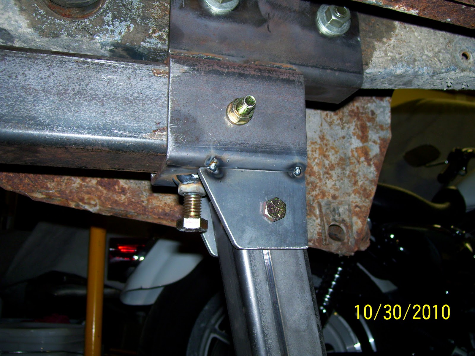
Here is a shot of the right rear frame bracket and slip collar that bolts into the factory frame tie-down bracket bolt holes.  The rear dolly bracket tabs have not yet been welded to the bracket slip tube in this photo.
 
The Mustang has a small bent flange at the very back of each rear frame tube that must be cleared by the body brackets to prevent damage.  I used careful selection of material thicknesses to provide clearance for these flanges.

A view of the flange clearance from the rear of the car.
 
The left side frame bracket and slip collar in place.

The rear frame assembly bolted in place.


Here is the mast of the front frame dolly caster.  I used two u-bolts to secure the mast to the factory crossmember.

Here is the completed dolly bolted in place before the jacking point was installed.  Notice the forward braces extend to plates bolted in the swaybar mounting locations on the frame for strength and stability.

Here is the jacking point in place on the mast.  As I discovered later, this point is better placed on the back of the mast rather thn the front.  I will make this modification over the winter so it's correct by spring.

Here's a better view of the whole front dolly assembly with the jacking point (see note above about jack point placement).  With a three-point dolly (e.g., one caster in front and two rollers in back), the frame will always sit squarely and securely on the garage floor and no twist will be imparted into the frame from an uneven garage floor.

Left rear upper dolly brackets tacked into the rotisserie frame bracket assembly.

Here is the complete rear dolly assembly mocked-up at the right rear.  Everything fits perfectly!


A close-up of the upper front brace mounted to the factory swaybar mounting location.

Lower rear mounting tabs clamped in place and ready to be tacked.

Rear dolly mocked-up, viewed from the rear.

Finished rear dolly close-up of the left rear.

Finished upper left dolly mount.  Nice clearance to factory fuel line.

The dolly rolls very well, even on rough concrete.

This gives you a good idea of the layout of the tri-pod dolly combination in use.

Rear dolly frame on jack stands getting rear to be docked into rotisserie frame.

I ended up adding two small pieces of 2x4 lumber between the dolly beam and jack stands to add a smidgen of height so the rear rotisserie frame would dock more easily.  I will add a couple of steel tube sections to the bottom of the cross bar to replace the wooden spacer blocks for future use.  Otherwise, there were absolutely no issues.  The trick here is to get the rear of the car up to docking height, then move to the front and get it jacked up and docked.  Once the front is secured, you can move to the back and finish docking the rear frame.

Front rotisserie frame mounted to chassis.  I will be moving the front dolly jack point to the rear of the dolly for improved access and ease of use.  Otherwise, one floor jack will lift the chassis to the proper height to dock into the rotisserie frame with travel to spare.


Once the front rotisserie frame is docked, the rear frame can be docked and the center spar clamped in place.  Once everything is locked down, the dolly's can be removed from the body.

First roll test and the rotisserie performed beautifully!

Another view of the body rolled 90 degrees and locked in place.

Funny how odd things look from this perspective.......

Great shot of the surface rust on the roof...........*sigh*