Tuesday, June 5, 2012

How To: Eat an Elephant

Another month has passed beneath the old chassis and I am slowly acclimating to the slower, more deliberate approach toward making progress on my Boss.  Inversely, I have “water over the gunnels” to an extent as I have endeavored to evolve the design and execution of the 4-link rear suspension to better compliment the proven function of the coilover front suspension I have for the car. 
Balance:  That’s the word.  The goal is to create a beautiful balance between the function and performance of the front and rear suspension systems.  As with most things, it is rare that those two systems are equally contributory in the equation when modifying a vehicle in the way that I (and countless others) have chosen to do.  I will not be satisfied unless my car performs as well as planned. 
Perhaps that is one of the reasons that draw “car guys” to the art.  Perhaps it is one of the last remaining frontiers where your “art” is as individual as your signature.  It becomes a part of you; a physical manifestation in metal and glass that represents who you are to a certain degree.  Whatever it is, I have come to love everything about it………..oh so many things.
The last month has been a flurry of small activities that are finally starting to show results of a larger proportion……with a few twists in between.  The biggest disruption to progress was a somewhat unexpected week in Europe dictated by my “day job” working on the new SRT Viper V10 engine program.  But hey…….a guy’s gotta do what a guy’s gotta do.
Custom Bilstein Rear Coilovers
A few months ago, I had the opportunity to run the rear shocks included in my 4-link suspension kit on the shock dyno and determined the damping curve to be less than required to achieve the suspension performance I required.  Further, the progressive rate rear springs were also not quite what I needed to get the system working together with the front suspension.  Since the “kit” shocks cannot be adjusted and the “adjustable” shock options that were offered were less than impressive, I decided to have a set of custom made Bilstein shocks made that would fill the bill and allow more adjustability on ride height as well as damping forces.  While the cost to do this would be rather considerable, the end result will be a much higher quality damper system that will match the front suspension in performance and function (read: Balance).  Coupled with that, these new shocks will allow me to use off-the-shelf racing coil springs of the exact rate I need to match the front suspension frequency on the dot.
After a few months of waiting, the shocks finally arrived and I am happy to report they look fantastic!  I will need to make some minor changes to the mounting scheme at the top and bottom, but they will fit like a glove and should work extremely well.  At the same time, I upgraded the spring seating hardware at the top and bottom of the shock to much higher quality pieces with some nifty features for good measure.  At this point, I am very happy with the shock combination I have and feel confident that with careful selection of the rear coil spring rate, I can get the suspension system working better than would have been possible using lesser components.

The custom made Bilstein rear coilover damper that I now have will replace the less capable damper shipped with the 4-link kit I purchased.  You can see the vastly increased ride height adjustment range in the Bilstein threaded body and each end of the damper has a precision spherical bearing rather than a comparatively soft bushing.  Everything about the Bilstein speaks of quality and capability and when valved to the application, this combination should be an outstanding performer.

If you like "cool" like I do, you will appreciate these adjustable spring seats.  This small cantilevered locking tab is simply toggled to allow most ride height adjustments to be made without tools and when the perfect height is set, you simply close the tab to lock the spring seat to the shock body.  Brilliant!

With the locking tab closed the spring seats are securely locked to the shock body.

Race quality parts on the street.  These upper spring seats appear on all four corners of my car and include these "diaper pin" safety clips on each upper spring seat location.

Steering Column Upgrades for Rack & Pinion Steering
As progress ebbed and flowed on rear suspension work, I decided to tackle some changes to the steering column configuration required for the future installation of a rack and pinion steering system.  The supplier of the steering kit included a needle bearing and support for the lower steering shaft that looks nifty in concept.  However, the idea of running a needle roller bearing directly on a mild steel, unhardened, welded seam steering shaft goes against everything my engineering mind could handle. So, in my usual “if-I-don’t-like-it-then-I’ll-invent-it” method, I designed up a ball bearing shaft support that uses a conventional, readily available ball bearing that fit the bill nicely and ensured the lower steering shaft would not be required to sacrifice itself as an inner bearing race, risking future failure with little warning.  This also keeps the bearing easily serviceable.  After a few hours on the lathe, the bearing and support were assembled and fit to the steering column with great success.  I finished the job by installing the universal joint included in the kit (nice piece) and the upper steering shaft and bearing.  The column now turns very freely and quite smooth with minimal effort.
I positively hated the lower steering column bearing solution supplied with the rack and pinion steering kit I purchased.  As such, I designed and machined my own solution.  My design uses an off-the-shelf double sealed ball bearing for shaft support and is pressed into the bearing holder.  The whole assembly is then bolted into the lower column tube for a secure assembly.  This shot shows the complete bearing holder assembly ready to bolt into place.

From the back, you can see the details of the holder and retention screws.

I prepared the inside of the column tube with a tootsie roll sanding plug on my die grinder to remove all burs and weld seam fuzz.  I drilled the three mounting screw holes prior to powder coating the tube.

Here is the lower steering shaft bearing assembly bolted into place.

And finally, the lower steering shaft universal joint is installed per the rack and pinion kit instructions.

A close-up view of the lower shaft bearing / u-joint interface.

New HTP Invertig 221 AC/DC Inverter Welder
Yep…..I finally pulled the trigger.  After several years researching and driving TIG welders of all shapes and sizes, I finally took the plunge and purchased a new, inverter-based, TIG welder!  I am not sure I have ever researched a tool purchase more than this one to be honest.  At the end of the day, I wanted to be sure I made a purchase that offered the maximum capability available with the best customer support, warranty and reliability.  At the same time, I have closely monitored the evolution of inverter-based welders and became convinced that the increased capabilities and features of an inverter were worth the extra investment, but the penalty was a cost factor roughly twice what a conventional transformer machine would carry. 
I researched all of the major welder offerings from Lincoln, Miller, ESAB, Hobart, etc. in both transformer and inverter designs.  I eventually drove all of the machines I could get my hands on and can say that none of the name-brand machines were particularly deficient in any area.  Some were definitely easier to use than others and some had more “little’ features than others, but all were pretty good overall.  Ultimately, I purchased the top-end Invertig 221 offering from HTP.  This machine weighs a scant 40 lbs. yet packs a whopping 220 amps of welding power.  Also, every single part of this machine is absolutely top quality; from the CK #17 torch, to the finest pedal I have ever seen on a commercial machine, to the best ground clamp in the business.  No junk here!  With a little study in the manual, I was able to light up on some steel scrap in the shop with little drama and start laying reasonably decent beads straight off even though it’s been over 20 years since I last drove a TIG machine regularly.  This machine is truly impressive.
HTP is an American company headed up by a straight-shooting gent named Jeff Noland.  I met Jeff a few years back at a trade show and he allowed me to drive all of his welder offerings and answered any questions I had.  To this day, I have been able to get Jeff on the phone whenever I had need to and he has always come through with answers in a most professional manner.  In fact, everyone on his staff that I have ever dealt with was exceptionally helpful.  Couple this level of customer service with an outstanding, no-questions-asked, warranty AND a machine that outperforms all other machines in its class and the combination is one I felt very comfortable investing my hard-earned bones into.  Check out HTP here:  HTP Invertig 221H
Knowing that a lot of the remaining work ahead of me will require more welding precision than a typical MIG welder can provide, I can now focus on learning the intricacies of this new TIG machine in preparation for the more delicate work ahead.  And you never know…….it might come in handy down the road on a “paying” job.  In the meantime, I plan light-up on just about everything I can to get into the groove of TIG welding as quickly as possible.
There it is!  The HTP Invertig 221H is a compact and very powerful TIG welder that took me several years to justify.  Now I have it and I am thrilled to get to work!

The simple control panel is very high quality and is protected by a polycarbonate shield when welding.

At only 40 pounds, this TIG machine is remarkable small, even compared to my Lincoln PowerMIG 180C MIG welder.  But don't let the size fool you!  This machine packs a full 220 amps of welding power yet only requires a 30-amp breaker.  Nifty stuff!


So as the title suggests, as my frame of reference continues to refine itself and I realize the cumulative progress that is made by linking all the little jobs together, I have discovered the secret to eating the proverbial “elephant”:
One bite at a time.

Thursday, May 10, 2012

9-Inch Rebuild: Locked Down Diff

Last month, I posted some pictures of my 9-inch differential section as I was tidying it up for a rebuild.  I was very lucky to have good and rare 9-inch differential “cores” to work with even if getting all the correct pieces in place was a bit more effort.  But a little due diligence resulted in acquiring top-shelf parts to perform the rebuild with confidence and a small measure of pride mixed in.

In the middle of working on the rear suspension, I finally started putting the differential (a.k.a., Pig, Hogshead, third-member, diff, chunk, carrier, etc., etc.) back together with brandy-new shiny parts.  On the menu for this center section is a new 3.89 ring and pinion from Motive Gear, new Timken bearings everywhere, a Raetech solid pinion shim kit, an Eaton Detroit Locker (a.k.a. “soft locker”) differential, all stuffed in my original nodular iron case and finished off with a genuine Daytona pinion support.  This is just about as bulletproof as any factory 9-inch ever got.
Now, I won’t go through the details of a complete 9-inch rebuild as there are many good resources for that information already, but I will touch on a few things that I did and/or learned along the way.  In fact, for anyone contemplating a 9-inch rebuild, I would recommend checking out the video tutorials available from Ken Collins at Bad Shoe Productions.  Ken is a talented and very experienced Ford Master Technician and he shares his vast knowledge in affordable, easy-to-follow educational videos.  Look him up and tell him I sent you.  You won’t be sorry!

In the meantime, I am very happy with how the rear axle assembly is shaping up and I enjoy the feeling of confidence that I have knowing I spared no effort in getting the “right stuff” in place.
There's quite a bit of work involved in proper setup of the pinion & support, particularly in getting pinion bearing preload just right.  The important lesson I learned in setting up the solid pinion spacers on 9-inch differentials is to bring it up to full torque on the pinion nut to check the preload.  Some spacer manufacturers recommend a much lower (approx. 130 ft/lb) nut torque and this simply does not work.  I used 200 ft/lbs on the pinion nut and the preload worked out perfectly.

Ring gear bolt torque is another detail that you get wildly different specs on as well as opinions on the use of thread lock compound (a.k.a. Loctite).  My experience has been to always trust the factory service specifications for ring gear bolt torque and use no Loctite on these fasteners.  Why?  Because torquing ring gear bolts is a relatively slow process that should be done in steps until final torque is achieved.  Believe it or not, Loctite will begin to harden within seconds of placing a bolt in a hole and this is not conducive to accurate torquing when the process lasts more than a few seconds.  Besides, a properly torqued (stretched) bolt should not require thread lock in most cases.

When dealing with several torqued fasteners, it is difficult at best to keep track of every bolt that has been torqued.  My favorite way to help me ensure I don't miss a bolt is to apply a paint mark to the bolt head and mating surface immediately after final torque.  This also works very well during maintenance inspections to ensure none of the torqued fasteners have moved.

Most ring and pinion sets are shipped with a rust preventative coating on the gears.  This coating needs to be removed before installation to prevent any problems with gumming and to make sure you get accurate gear contact pattern representations when doing your final gear mesh checks using gear marking compound.  I like to use lacquer thinner to remove all of these oils before installing the ring and pinion gears.

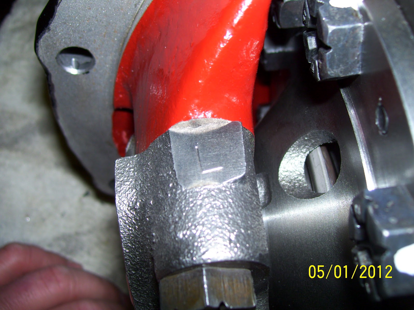
If you happen to be the first person to rebuild a particular 9-inch differential, chances are, the main caps will not be marked as to their proper location in the case.  Since these caps are machined to match the case, they cannot be mixed up (just like crankshaft main caps in an engine).  Therefore, it's a good idea to mark the caps before removing them to ensure they are returned to their proper location during rebuild.  In this shot, you can see this cap is marked with a large "L" to indicate this is the LEFT (or driver's side) main cap.

In similar fashion to the above photo, this cap is marked with a large "R" to indicate this is the RIGHT (or passenger's side) main cap.

Proper 9-inch case setup is not [possible without some accurate means of turning the bearing adjusters.  I made this simple pin spanner wrench out of some 1/4" flat stock and 5/16" rod and welded up two wrenches in a few minutes.  You could easily make something similar using a pair of 5/16" bolts if welding capabilities are unavailable.

Backlash settings are one area where the gear manufacturers specs must be followed to the letter.  Depending on the gear machining and finishing processes used by the manufacturer, the backlash targets can vary by several thousandths of an inch.  In my case, I chose a gear set from Motive Gear, who laps both the drive and coast faces of their gears during final manufacture.  This is rather unique and allows backlash targets to run slightly tighter than many factory and aftermarket gears.  My average backlash (measured at three locations around the gear) was set at 0.010".

While many gear manufacturers reference a measured pinion depth, it is rare that using this dimension alone will create the ideal pinion depth.  I have found the best option is to start with the pinion shim that came with the differential housing from the factory (if possible).  Nine times out of ten, this will nail the pinion depth on the nose.  Ford always references the "master case depth" specification in their pinion shim establishment, so using the same thickness pinion shim as installed from the factory is always the best place to start.

In this shot, you can clearly see an almost perfect gear pattern on the drive face of the gear.  The contact is perfectly centered from the toe to the heel of the tooth as well as from the root to the tip.  It doesn't get much better!

On the coast face of the gear, the pattern is again almost perfect.  The contact is biased slightly toward the toe (e.g., the inner diameter) of the gear tooth and is well centered from root to tip.

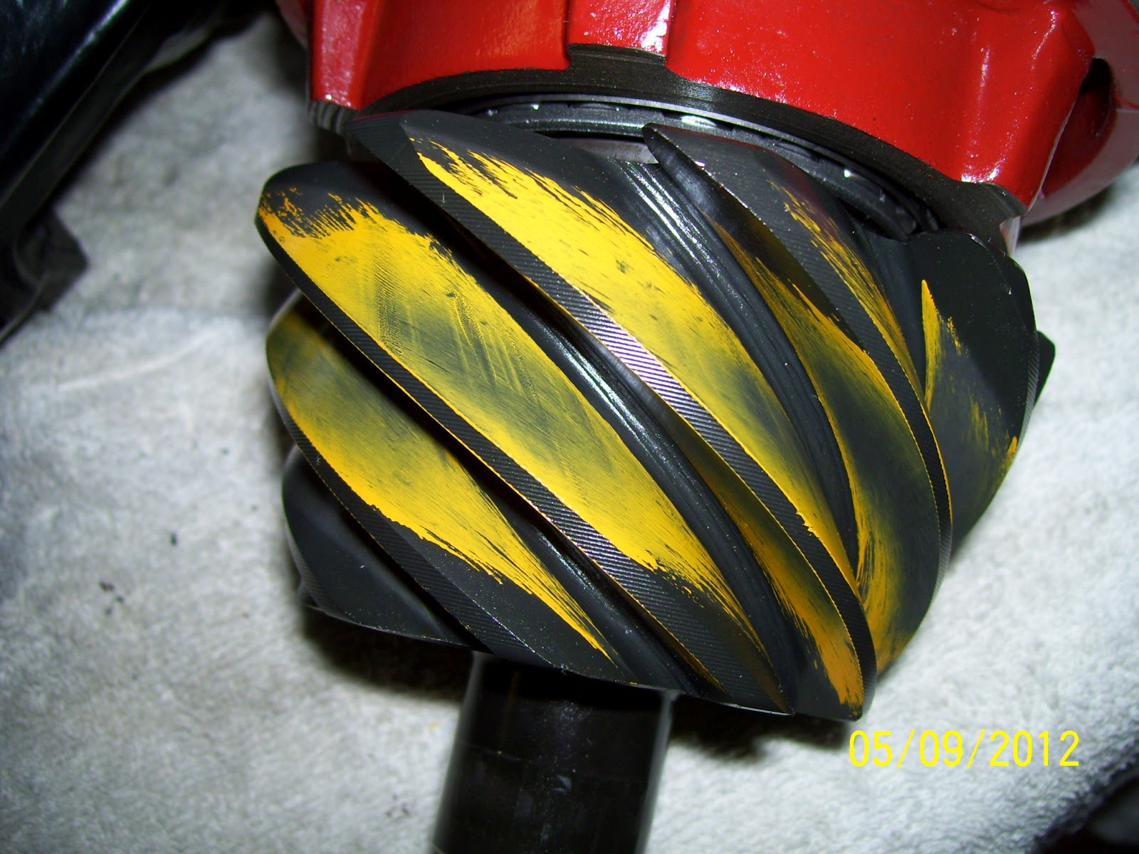
While not generally something that is referenced in gear pattern charts, the pinion contact should also be well centered over the entire tooth face, similar to the ring gear.  Here is the coast side faces showing a nicely centered pattern.

And here is the drive side faces showing excellent contact position as well.

Thursday, May 3, 2012

4-Link Bracket Update

When I last left off, I had the rear 4-link brackets positioned and tacked into place and had successfully mocked-up the housing in the car.  After several nights of measuring everything, I decided to fully weld the brackets into place and moved on to fitting the panhard rod bracket to the axle.

After a little bit of trimming and fitting and careful positioning of the bracket, I tacked it into place and verified the fit in the car.  As fortune would have it, the panhard rod fit very well and I could now weld everything fully.  With all of the axle brackets fully integrated into the axle housing, I headed back to the car for another fit test and attached everything one more time.  Again, I was very happy that everything looked to be in good order and I am now feeling a good bit more comfortable with the state of affairs in the rear suspension. 
There is still a lot left to do, but I am concentrating on getting the differential assembled and the axle housing outfitted with a new axle vent, right side brake line mount tab, left side distribution block mount, relocation of the brake hard line tabs and machine the integrated axle jack point / drain bung.  Once I get all of that squared away, I will prep the housing for powder coat, assemble and install the rear calipers, rotors and flexible brake lines and bend up the stainless hard line.  That should button up the axle assembly and allow me to concentrate on the rest of the rear suspension modifications (which will be fairly numerous).  Should be interesting when I’m done!

I don't think these brackets will fall off.  Once I had the 4-link brackets fully welded, I could concentrate on the panhard bracket.


After a few trial fits and tacking into place, I welded the panhard bracket in place.

Another look at the panhard bracket after welding.

With only a little clean-up, these welds will show nicely after powder coat.

Here is a shot of the left side brackets complete and mocked up in the car.
 
I just love how purposeful and "all-bidnez" this rear suspension looks under the car.

Looking toward the right side of the car, you can clearly see the panhard in place.

Thursday, April 26, 2012

Seat Sneak-Peek

Seats have to be one of the toughest things to choose for a hot rod muscle car.  Like custom wheels, it’s way too easy to pick a seat style that looks too “Ricky Racer” and fails to blend in with the interior of the car.  I like interiors that are “subtly modern” with styling cues that are easily identifiable to the original interior of the car.  For this reason, I have struggled to find a seat combination that looked nice, with a modern flair, but still kept some identifiable relationship to the original high-back bucket seats that were common in 69-70 Mustang interiors.

About a year or so ago, I saw few pictures of a 69 Camaro done out on the west coast that had a pair of seats that I thought might just do the trick.  Since the fellow who built the car was a friend of a friend, I asked second-hand, who made the seats he used.  I was shocked to learn they were seats taken from a 2011 Honda CRZ Hybrid!  Oh the humanity!

With this information in hand, I set about looking for a pair of seats to see how they might fare as candidates for my Boss 302.  After a year of searching, I found a pristine pair of seats locally (almost) for a fantastic price from a salvaged car with only 13 miles on it!  Score!

Once I got the seats home and started comparing the styling, dimensions and features to the old high-back buckets, I felt I had found the perfect seat option for my car.  If you can imagine the center panels in perforated black suede leather with the sides and headrest done in matte finish smooth black leather, you will quickly see how these seats will take on the appearance of a modernized Mustang high-back bucket.  After a bit of simple fabrication for seat mounts, these seats will bolt into the stock seat locations and should work fantastic!
Side by side, the Honda CRZ seat looks surprisingly similar to the original Mustang high-back bucket seat.  Proportions are very similar.  Hmmmm.....maybe a Boss 302 logo embroidered in the upper shoulder panel or headrest?

Without the often HUGE bolsters of many aftermarket seats, the Honda CRZ seat has very approachable styling that should work well with the 69-70 deluxe interior styling.........modernized of course.

Interestingly enough, the old high-back seat bottom is almost a full inch wider than the new seat.

Comparing the lower seat backs, you can see that there will be no concern for fit in this area.

Another look at the similarity in design of the old vs. new seat.  I'm lovin' this look!

Thursday, April 19, 2012

4-Link Bracket Work & Mock-Up – If it was easy, everybody would be doing it

In the middle of lots of non-Boss related work bleeding my time away, I have managed to make some progress on the rear 4-link coilover suspension…….and learned some valuable lessons along the way.
For several weeks, I have been trying to resolve a problem I discovered with the 4-link brackets that are included with the Heidt’s 4-link coilover suspension kit.  Quite simply, the brackets that are supplied were made for a 3” axle tube diameter which no classic Mustang ever came with (3” axle tubes are a popular aftermarket housing thing).  In 2011, I had an email contact at Heidt’s that I was communicating with on other things and decided to see what could be done to exchange the 3” OD brackets for the properly sized 2.75” brackets I needed.  After a number of tries, I was getting nowhere fast and ended up calling the dealer I bought the kit from (Tim’s Hot Rods) at Heidt’s recommendation (their policy).  Tim Stromberger (fantastic guy!) had never heard of the problem I was having so I explained Mustang axle tube sizes to him and he made notes for future reference.  He called Heidt’s on my behalf and I got set up with a new contact, much higher up the food chain than the individual I was originally working with (who evidently was no longer with the company).  After a few conversations back and forth and some philosophical point and counterpoint, I learned that Heidt’s had “small” tube brackets they offered in the instance that the supplied brackets didn’t fit, so I jumped on that like Rosie O’Donnell on a doughnut.
A few days later, the “smaller” brackets arrived and I realized my first error:  In my excitement to solve the problem, I didn’t specify what axle tube size I had and the brackets that were sent were for the rare and ultra-small 2.5” axle tubes.  S*(&^%#T!  Another few phone calls and we determined that the proper 2.75” brackets did not (yet) exist to allow a stock 9-inch Mustang axle housing to be used with the kit.  Apparently, most of the kits Heidt’s sells include their axle housing option with the brackets pre-installed and this never came up before.  So, the guys at Heidt’s went back to the drawing board and produced a new set of brackets for my 2.75” axle tubes and sent them my way in about a week and we were in business (thanks Mike)!
So, the lessons learned are rather simple.  Never again will I get so complacent with the ease and convenience of email communication.  When technical issues arise like this, I will be much quicker to pick up the telephone and persist until I talk to someone who can help (what’s old is new?).  This same policy should apply when ordering parts to make sure what is offered will in fact fit “out-of-the-box” or if certain models may require alternate parts. 
Secondly, never assume a parts manufacturer knows more about your car than you do.  As much as we may like to believe that every supplier is an expert on the intricacies of our beloved ponies, this will rarely be the case as they are often in the business of offering parts for many different makes of vehicle, making absolute expertise nearly impossible for them to approach. 
And third, you never know what benefit may come from running a problem all the way to ground such that a genuine solution is found.  As frustrating as the process may have been, the end result from this rather protracted exercise is the satisfaction in knowing that Heidts can now supply Mustang 4-link axle brackets to fit 2.5”, 2.75” and 3.0” axle tubes, and that is good for the market in general.  Now, let’s get on with it…..
 After getting some of the minor repairs completed on the axle housing and in between stints working on the 9-inch center section, I was finally to the point that I could get the housing brackets tacked into place and the system mocked up in the car to verify fit (and entertain myself good bit as well).  A digital angle finder was indispensable in easily getting the bracket angles perfectly set to allow me to tack them in place.  This is definitely a 2-person job and my bestest buddy and partner in crime (a.k.a. Dad) put up with my endless fiddling and fussing to help me get things just right.  Once we had the 4-link brackets positioned and tacked into place, it was time to see what the setup would roughly look like under the car, bearing in mind that the panhard bracket could not be mocked-up as that can only be put in place after the 4-link brackets have been permanently welded.
With the car on its side in the rotisserie, we were able to easily place the empty axle housing in place while we loosely hung the short and long links as well as the top coilover mounts.  With the axle basically located, we loosely connected the lower coilover mounts and rolled the car level to have a look at things.  And like so many other things we have completed on this car, the look of the coilover rear makes me smile……big.  In simple street terms……it looks pretty bad-ass and will be even better when it is completed.
I have a lot of work left in the rear suspension and several modifications I plan to make (much to Heidts’ chagrin I am sure) to improve the suspension’s roll-bind characteristics and allow much easier suspension setup, alignment and tuning.  Those modifications will of course be documented here, but at least for now, I can move forward with the remaining housing modifications, sandblasting the housing, continuing the build of the 9-inch differential, rear caliper rebuilds and installation, brake hose and hard line routing and powder coating the whole works.  So in short, I am plenty busy, even though it doesn’t really LOOK like it at the moment.  More to come!
With the help of my Dad and a nice digital angle finder, tacking the 4-link brackets to the housing was not difficult.  This is the view from the front of the housing where the 4-link bars connect.

From the back, the brackets are quite tidy looking.  The three holes at the lower part of the photo are where the bottom of the coilover shocks mount.

With the car on it's side in the rotisserie, it was a easy job to loosely hang all of the parts on the housing and the chassis for mock-up purposes.

Here is the lower arm chassis mount without the steel spacer installed.  Since I will be reconfiguring this entire end of the arm, the finished installation of this connection will look completely different than this photo.

I can't help but like the look of this suspension under the car.  It is quite a motivator to see things start to take shape.

Another shot showing the simple functionality of a compact 4-link coilover rear suspension.

Wednesday, April 18, 2012

Back in Black – Oxide, That Is

Being certifiably out of my mind, when I endeavor to do strange and unusual things in my shop, it rarely raises any eyebrows.  However, my latest little foray into the unknown has a few of my car-guy buddies rather enthused.
Specifically, I spent several months complaining about the apparent difficulty and cost associated with getting parts coated in black oxide for corrosion protection and good looks.  It’s not that it can’t be done locally you understand (I’m all about that whenever possible), it’s the entire headache of the experience, from cost, to “down-time” to cost……..you get the idea.

So, I set off to research what options were out there to accomplish this type of work on a smaller, more affordable scale at home.  Pretty quickly, I found there are basically two players in the “aftermarket” that offer viable black oxide kits:  The venerable Eastwood Company and Caswell Inc. 

As much as I appreciate the efforts of the Eastwood Company to support our hobby, my personal experience with most of these types of “kits” they offer has been anything but shining.  On the other hand, I have dealt with Caswell for several years on powder coating matters and find everything they offer to be top shelf and have never been disappointed.  With little hesitation, I purchased Caswell’s 1.25 Gallon Black Oxide Kit and waited only a few short days before it was at my door.  This kit was particularly interesting to me based on the fact that it was a “cold” process as opposed to the old standard “hot” process.  This technology was pioneered by the gun industry and the finish is found on countless firearms in almost every conceivable form.

The kit arrived very well packed and was rather surprising in its simplicity.  The instructions were very easy to follow and with a few gallons of distilled water on hand, I was able to get started with my first batch of parts within minutes.

The simple process involved mixing the blackening agent with distilled water in the supplied 1.5 gallon bucket.  Then, as simple as you please, I submerged my freshly blasted pinion support bolts as well as a tapered snap ring installation sleeve I made to help in rebuilding Ford Cobra Mustang rear brake calipers (long story).  I used an old pair of long needle nosed pliers to place and retrieve the parts in the solution with the total submerged time of less than 5 minutes total.

The parts emerged from the solution a wonderful, even and very attractive black oxide finish, ready for sealing.  The protective, penetrating sealant supplied in the kit is an oddly oily dark amber fluid that smells a bit like shellac.  A quick 5-minute bath in the sealant was all that was required and I set the parts to the side for a few days to allow the sealant to penetrate and dry per the instructions.  A quick drying off with a paper towel revealed perfectly uniform and evenly blackened parts with absolutely no headache whatsoever.

Since I have many more small parts I want to finish in black oxide, I expect to get a lot of use from this inexpensive and easy-to-use kit from Caswell.  The packaging allows you to preserve the solution in the bucket it is shipped in and that makes storage between uses quite painless.  So far…….I’m a big fan!
Here is the Caswell black oxide kit ready for use.  The parts in the foreground are my intended victims:  my 9-inch pinion support bolts as well as a tapered snap ring compressor I made for assembling Cobra rear brake calipers.

I was half-way expecting complicated instructions with the kit, but I was pleasantly surprised at their simplicity.
 
Caswell supplies two cans of their penetrating sealant that is to be applied immediately after the blackening process is completed.

The mixed blackening solution has the appearance of light blue, slightly soapy dishwater with almost no odor at all.

I had to laugh a bit as the solution quickly blackened the pliers I used to retrieve the parts after the prescribed treatment time.

Here are the pinion bolts after about 3 minutes of soak time in the blackening solution.  As you can see, they are already very well coated in black oxide.  I followed the bolts up with the tapered sleeve tool I made and the results were equally impressive.

If you look closely, you can just make out the tapered sleeve at the bottom of the can of sealant.

And here are the parts fresh out of the sealant and ready for the drying phase.  The finish is excellent and once dry, the parts look every bit as nice as any commercial black oxide coating I have seen.