Tuesday, July 24, 2012

Rear Disc Brake Fitting, Brake Lines & Coilover Mount Bushings

As the rear axle evolution progresses, I am becoming more and more happy with the results.  After a few nights of diligent work, I am to the point where I will start prepping the axle housing for final color very soon, and that will make way for the final modifications to the 4-link suspension.  However, before I get too far in that description, there are a few interesting things I need to document here first.
“Cunifer” Hard Lines
Pronounced “Cue•knee•fur” – the word cunifer is actually an acronym referring to the metallic composition of the brake line tubing most people have never heard of.  Specifically, cunifer tubing is an alloy of copper (Cu), nickel (Ni) and iron (Fe) and has been around for over 70 years.  The material is extremely corrosion resistant, bends and flares very easily, and is very durable.  And while the material is a copper-based alloy it is NOT conventional copper plumbing tubing in any way, shape or form.
In hot rod circles, stainless tubing gets big play because it’s shiny, durable, and obviously corrosion resistant.  The good news is that many pre-bent brake line kits are available in stainless for restoration ease as well.  But what if you are doing something from scratch or want to clean-up the appearance of the installation over what the factory installed?  In most cases, you are on your own, and generally speaking, stainless steel brake tubing is harder to work with and expensive, especially for the do-it-yourself restoration enthusiast.  In fact, other than “off-the-roll” appearance, there really isn’t any advantage to stainless steel brake line material compared to cunifer. 
When was the last time you saw stainless steel brake lines on a production car?  Even an exotic, high-end sports car for that matter?  Fact is, in 99% of brake applications, they don’t use stainless brake tubing.  In fact, more high-market car manufacturers use cunifer tubing than any other.  Rolls-Royce, Porsche, Audi, Aston Martin, and Volvo all use cunifer brake line tubing exclusively.  Japanese and US car manufacturers are the remaining hold-outs that continue to use conventional coated steel (not stainless) tubing due to the pervasive “low-bidder” mentality that dominates these markets.
Luckily, cunifer tubing is easy to get in the aftermarket and is priced between plain coated steel and stainless steel tubing.  It can be easily polished to a copper-silver shine (if that’s what you like) and will accept all standard brake hardware.  Due to cunifer tubing’s slightly softer surface than steel, an additional measure that should be taken is that the outer surface of the cunifer tubing should be protected with a stainless steel spring shield to avoid damage from rocks and road debris.  Plus it looks kinda cool as well!  I have chosen cunifer tubing as the preferred material for all of my fluid hard lines in the Boss and formed the rear axle hard line using this material.  I will be using much more of this material as I move forward in routing new brake hard lines around the rest of the car and will likely use it for the fuel hard lines as well.  In any case, it’s worth a look.

Cunifer brake tubing is wonderfully easy to form with simple tools.  Note the protective stainless steel spring around the tubing to prevent damage from road debris.
Here is the rear brake distribution block with the newly formed cunifer hard line in place.
  
The hard line is routed around the periphery of the 3rd member for a clean look.

Here is a look at the passenger side of the hard line.  Bends are smooth with no hint of kinks.

Rear Disc Brake Trial Fit
As the modifications to the axle housing approach completion, the time had finally come to trial fit all of the Street or Track, LLC rear disc brake conversion parts I had collected for the car to ensure everything fit as intended and clearance issues could be addressed before applying final finishes to the rest of the parts.  This would also mark the first time I could test fit the axles and complete set of brake lines to the housing as well.
I am happy to say that the brake kits installed quite nicely and the installation instructions were quite easy to follow.  I played with caliper position a bit but quickly discovered there was only one position that would allow adequate clearance to all components, so that’s what I stayed with.
Once I was satisfied with the caliper installation, I fit all of the rear brake lines (hard and soft) to ensure proper fit.  Here again, the Street or Track parts worked superbly and I could now move forward with final prep of the housing before sand blasting and coating.
This is the Street or Track rear disk brake kit mocked up on the left rear of the axle housing.  This is the "busiest" corner of the car and I discovered the fit to be perfect for my 4-link suspension.

here is the left rear brake kit installed (without brake pads).

The right rear brake kit is equally nice an installation and a considerably less crowded corner than the left.

Left rear disc brake conversion mock up is complete!

Coilover Lower Mount Bushings
In the process of engineering the upgrades to the 4-link rear suspension I am installing, I moved to a custom made Bilstein damper.  In doing so, the mounting fastener diameter went from 5/8” to ½”, which necessitated bushing the mounting holes in the axle brackets down to the proper size.  As luck would have it, I found commercially available bushings at a local hardware store that fit the bill perfectly.  With a quick pass of a 5/8” drill through each hole, the bushings slipped right in and I was able to weld them in with little trouble.  Another quick pass with a ½” drill and the lower mounts were ready for action.  Check!

Using a commercially available bushing, I was able to weld it into the original 5/8" mounting holes.  This was necessary to mount the new Bilstein coilover dampers as they use 1/2" fasteners instead.

Going Forward
Now that the mechanics of the axle housing are basically complete, my next area of concentration will be to finish modifying the rear trailing arms and fabricating the spacers required to properly locate the spherical rod ends that will replace the rubber bushings they were originally configured with (yuck!).  Following that, and a few more trial fits, the axle housing should be ready for color and the brakes can be finally fit.  By this time, Fall should be approaching and the focus will shift back to the rear bodywork area and then the fitting of the front coilover suspension.  Busy winter ahead!  …….and still a few surprises to come!

Tuesday, July 3, 2012

Axle Housing Updates

The month of June has come and gone and I’m happy to say it’s been a very good month, even though my work volume on the car doesn’t outwardly reflect it.  Early in the month, I was fortunate enough to take a “real” 2-week vacation with my lady to visit my family in northern Germany and enjoy the many sights available in and around the area.  I hadn’t had a vacation to speak of since about 1996 or so and this trip reminded me how important it is to breathe the throttle once in a while to recharge and put everything back into perspective.  It worked….and I’ll not wait so long to do it again.
The last two weeks of June were spent catching up on business matters that developed while I was away and cultivating some new contacts that have the potential to advance this build more than I could have imagined.  While I won’t spoil the fun just yet, the next several weeks should generate some very exciting things, with a bit of “eye candy” to boot!
As has been the norm for the past few months, I have been concentrating on getting the rear suspension and axle set up under the car.  The custom Bilstein rear coilover dampers are finished and I am selecting rear spring rates as I write this.  I have also sourced all of the components and tools I will require to get the rear trailing arms upgraded to spherical rod ends to allow the 4-link to behave like a proper 4-link should.  While the expense to get the rear suspension system upgraded according to plan has been much more than I had anticipated, I am firmly convinced the results will be worth every cent.
On the “plus” side of the equation, I have been able to complete all of the required axle housing modifications.  The 4 link brackets are complete, the factory welds cleaned up, and the brake line tube tabs shaved.  But there are two modifications I made that I am particularly pleased with that are the feature of this entry.
First, I have always been irritated by the general lack of convenience in servicing gear lube in a 9-inch axle assembly.  Ford was kind enough to provide a place to put the lube, but never a place to drain it out.  I you’re like me, the cost of a few quarts of synthetic gear lube is worth the price of admission given the peace-of-mind I get from knowing the condition of the axle at any given time.
Additionally, the attractiveness of being able to jack the car up from the center of the axle housing is rather undeniable.  That is, until you see the mess a floor jack makes of the finish on the lower housing once all the convenience of the method is spent.  Since I will be powder coating my axle housing, I wanted to devise a way to have my cake and eat it too.  To that end, I designed and machined a combination axle drain and jack point that serves both purposes well.  Now, with a simple urethane jack pad on my floor jack cup, I can lift the car without damage to the housing finish AND drain the axle lube at any time with no more effort than I spend draining engine oil.
Next, I have always disliked Ford’s method of venting the rear axle housing.  The hose nipple and rubber whip hose protruding from the top of the axle tube always appeared very “busy” to me and generally unfinished.  Especially when you consider the nifty way they jam the free end of the vent hose into the upper rear shock bracing to keep it out of the way.  Nope…..that won’t do at all.
Borrowing alternate solutions from other manufacturers and builders, I decided to install a simple, tidy, sintered stainless steel vent fitting that would eliminate all of the production mess and provide adequate venting.  These vents are inexpensive and easily available and can be found on numerous aftermarket axle assemblies.  I chose an all-stainless steel vent for the uniformity of appearance as well as the durability factor and installed it in the location where the original vent nipple was placed.  A simple drilling and tapping operation and the deal was done.
So, as modifications go, there’s nothing earth-shattering here, but in the long run, I expect them to provide small conveniences where before there were none.  Just a few more details to set it apart.
A little time on the lathe is all it took to spin up this combination axle drain bung/jacking point.  Here is the final machining operation:  tapping the hole for the 1/2 x 20 drain plug.

The completed drain plug ready to go.  Note the flange at the base to allow a nice weld surface without distorting the tapped hole.

So simple yet so effective.  Here is the completed bung with the drain plug installed.  The weld flange can be easily seen at the base.

I positioned the bung on the bottom of the housing after drilling a 9/16" hole in the housing at the exact location I wanted the bung positioned.  Then I simply used the drain plug to hold the bung in place by screwing it into the bung from inside the housing.  You can just see the end of the plug inside the threaded hole in this shot.

A few minutes of welding and the bung is in place (still hot when I shot this picture!).

From inside, you can see the nice, clean drain hole with absolutely no intrusion into the housing like many alternative ideas advocate.

Complete and ready for sandblasting and powder coat!

This nifty little sintered stainless steel axle vent is all that will be visible rather than the nasty factory hose barb and rubber hose the factory provided.

Tuesday, June 5, 2012

How To: Eat an Elephant

Another month has passed beneath the old chassis and I am slowly acclimating to the slower, more deliberate approach toward making progress on my Boss.  Inversely, I have “water over the gunnels” to an extent as I have endeavored to evolve the design and execution of the 4-link rear suspension to better compliment the proven function of the coilover front suspension I have for the car. 
Balance:  That’s the word.  The goal is to create a beautiful balance between the function and performance of the front and rear suspension systems.  As with most things, it is rare that those two systems are equally contributory in the equation when modifying a vehicle in the way that I (and countless others) have chosen to do.  I will not be satisfied unless my car performs as well as planned. 
Perhaps that is one of the reasons that draw “car guys” to the art.  Perhaps it is one of the last remaining frontiers where your “art” is as individual as your signature.  It becomes a part of you; a physical manifestation in metal and glass that represents who you are to a certain degree.  Whatever it is, I have come to love everything about it………..oh so many things.
The last month has been a flurry of small activities that are finally starting to show results of a larger proportion……with a few twists in between.  The biggest disruption to progress was a somewhat unexpected week in Europe dictated by my “day job” working on the new SRT Viper V10 engine program.  But hey…….a guy’s gotta do what a guy’s gotta do.
Custom Bilstein Rear Coilovers
A few months ago, I had the opportunity to run the rear shocks included in my 4-link suspension kit on the shock dyno and determined the damping curve to be less than required to achieve the suspension performance I required.  Further, the progressive rate rear springs were also not quite what I needed to get the system working together with the front suspension.  Since the “kit” shocks cannot be adjusted and the “adjustable” shock options that were offered were less than impressive, I decided to have a set of custom made Bilstein shocks made that would fill the bill and allow more adjustability on ride height as well as damping forces.  While the cost to do this would be rather considerable, the end result will be a much higher quality damper system that will match the front suspension in performance and function (read: Balance).  Coupled with that, these new shocks will allow me to use off-the-shelf racing coil springs of the exact rate I need to match the front suspension frequency on the dot.
After a few months of waiting, the shocks finally arrived and I am happy to report they look fantastic!  I will need to make some minor changes to the mounting scheme at the top and bottom, but they will fit like a glove and should work extremely well.  At the same time, I upgraded the spring seating hardware at the top and bottom of the shock to much higher quality pieces with some nifty features for good measure.  At this point, I am very happy with the shock combination I have and feel confident that with careful selection of the rear coil spring rate, I can get the suspension system working better than would have been possible using lesser components.

The custom made Bilstein rear coilover damper that I now have will replace the less capable damper shipped with the 4-link kit I purchased.  You can see the vastly increased ride height adjustment range in the Bilstein threaded body and each end of the damper has a precision spherical bearing rather than a comparatively soft bushing.  Everything about the Bilstein speaks of quality and capability and when valved to the application, this combination should be an outstanding performer.

If you like "cool" like I do, you will appreciate these adjustable spring seats.  This small cantilevered locking tab is simply toggled to allow most ride height adjustments to be made without tools and when the perfect height is set, you simply close the tab to lock the spring seat to the shock body.  Brilliant!

With the locking tab closed the spring seats are securely locked to the shock body.

Race quality parts on the street.  These upper spring seats appear on all four corners of my car and include these "diaper pin" safety clips on each upper spring seat location.

Steering Column Upgrades for Rack & Pinion Steering
As progress ebbed and flowed on rear suspension work, I decided to tackle some changes to the steering column configuration required for the future installation of a rack and pinion steering system.  The supplier of the steering kit included a needle bearing and support for the lower steering shaft that looks nifty in concept.  However, the idea of running a needle roller bearing directly on a mild steel, unhardened, welded seam steering shaft goes against everything my engineering mind could handle. So, in my usual “if-I-don’t-like-it-then-I’ll-invent-it” method, I designed up a ball bearing shaft support that uses a conventional, readily available ball bearing that fit the bill nicely and ensured the lower steering shaft would not be required to sacrifice itself as an inner bearing race, risking future failure with little warning.  This also keeps the bearing easily serviceable.  After a few hours on the lathe, the bearing and support were assembled and fit to the steering column with great success.  I finished the job by installing the universal joint included in the kit (nice piece) and the upper steering shaft and bearing.  The column now turns very freely and quite smooth with minimal effort.
I positively hated the lower steering column bearing solution supplied with the rack and pinion steering kit I purchased.  As such, I designed and machined my own solution.  My design uses an off-the-shelf double sealed ball bearing for shaft support and is pressed into the bearing holder.  The whole assembly is then bolted into the lower column tube for a secure assembly.  This shot shows the complete bearing holder assembly ready to bolt into place.

From the back, you can see the details of the holder and retention screws.

I prepared the inside of the column tube with a tootsie roll sanding plug on my die grinder to remove all burs and weld seam fuzz.  I drilled the three mounting screw holes prior to powder coating the tube.

Here is the lower steering shaft bearing assembly bolted into place.

And finally, the lower steering shaft universal joint is installed per the rack and pinion kit instructions.

A close-up view of the lower shaft bearing / u-joint interface.

New HTP Invertig 221 AC/DC Inverter Welder
Yep…..I finally pulled the trigger.  After several years researching and driving TIG welders of all shapes and sizes, I finally took the plunge and purchased a new, inverter-based, TIG welder!  I am not sure I have ever researched a tool purchase more than this one to be honest.  At the end of the day, I wanted to be sure I made a purchase that offered the maximum capability available with the best customer support, warranty and reliability.  At the same time, I have closely monitored the evolution of inverter-based welders and became convinced that the increased capabilities and features of an inverter were worth the extra investment, but the penalty was a cost factor roughly twice what a conventional transformer machine would carry. 
I researched all of the major welder offerings from Lincoln, Miller, ESAB, Hobart, etc. in both transformer and inverter designs.  I eventually drove all of the machines I could get my hands on and can say that none of the name-brand machines were particularly deficient in any area.  Some were definitely easier to use than others and some had more “little’ features than others, but all were pretty good overall.  Ultimately, I purchased the top-end Invertig 221 offering from HTP.  This machine weighs a scant 40 lbs. yet packs a whopping 220 amps of welding power.  Also, every single part of this machine is absolutely top quality; from the CK #17 torch, to the finest pedal I have ever seen on a commercial machine, to the best ground clamp in the business.  No junk here!  With a little study in the manual, I was able to light up on some steel scrap in the shop with little drama and start laying reasonably decent beads straight off even though it’s been over 20 years since I last drove a TIG machine regularly.  This machine is truly impressive.
HTP is an American company headed up by a straight-shooting gent named Jeff Noland.  I met Jeff a few years back at a trade show and he allowed me to drive all of his welder offerings and answered any questions I had.  To this day, I have been able to get Jeff on the phone whenever I had need to and he has always come through with answers in a most professional manner.  In fact, everyone on his staff that I have ever dealt with was exceptionally helpful.  Couple this level of customer service with an outstanding, no-questions-asked, warranty AND a machine that outperforms all other machines in its class and the combination is one I felt very comfortable investing my hard-earned bones into.  Check out HTP here:  HTP Invertig 221H
Knowing that a lot of the remaining work ahead of me will require more welding precision than a typical MIG welder can provide, I can now focus on learning the intricacies of this new TIG machine in preparation for the more delicate work ahead.  And you never know…….it might come in handy down the road on a “paying” job.  In the meantime, I plan light-up on just about everything I can to get into the groove of TIG welding as quickly as possible.
There it is!  The HTP Invertig 221H is a compact and very powerful TIG welder that took me several years to justify.  Now I have it and I am thrilled to get to work!

The simple control panel is very high quality and is protected by a polycarbonate shield when welding.

At only 40 pounds, this TIG machine is remarkable small, even compared to my Lincoln PowerMIG 180C MIG welder.  But don't let the size fool you!  This machine packs a full 220 amps of welding power yet only requires a 30-amp breaker.  Nifty stuff!


So as the title suggests, as my frame of reference continues to refine itself and I realize the cumulative progress that is made by linking all the little jobs together, I have discovered the secret to eating the proverbial “elephant”:
One bite at a time.

Thursday, May 10, 2012

9-Inch Rebuild: Locked Down Diff

Last month, I posted some pictures of my 9-inch differential section as I was tidying it up for a rebuild.  I was very lucky to have good and rare 9-inch differential “cores” to work with even if getting all the correct pieces in place was a bit more effort.  But a little due diligence resulted in acquiring top-shelf parts to perform the rebuild with confidence and a small measure of pride mixed in.

In the middle of working on the rear suspension, I finally started putting the differential (a.k.a., Pig, Hogshead, third-member, diff, chunk, carrier, etc., etc.) back together with brandy-new shiny parts.  On the menu for this center section is a new 3.89 ring and pinion from Motive Gear, new Timken bearings everywhere, a Raetech solid pinion shim kit, an Eaton Detroit Locker (a.k.a. “soft locker”) differential, all stuffed in my original nodular iron case and finished off with a genuine Daytona pinion support.  This is just about as bulletproof as any factory 9-inch ever got.
Now, I won’t go through the details of a complete 9-inch rebuild as there are many good resources for that information already, but I will touch on a few things that I did and/or learned along the way.  In fact, for anyone contemplating a 9-inch rebuild, I would recommend checking out the video tutorials available from Ken Collins at Bad Shoe Productions.  Ken is a talented and very experienced Ford Master Technician and he shares his vast knowledge in affordable, easy-to-follow educational videos.  Look him up and tell him I sent you.  You won’t be sorry!

In the meantime, I am very happy with how the rear axle assembly is shaping up and I enjoy the feeling of confidence that I have knowing I spared no effort in getting the “right stuff” in place.
There's quite a bit of work involved in proper setup of the pinion & support, particularly in getting pinion bearing preload just right.  The important lesson I learned in setting up the solid pinion spacers on 9-inch differentials is to bring it up to full torque on the pinion nut to check the preload.  Some spacer manufacturers recommend a much lower (approx. 130 ft/lb) nut torque and this simply does not work.  I used 200 ft/lbs on the pinion nut and the preload worked out perfectly.

Ring gear bolt torque is another detail that you get wildly different specs on as well as opinions on the use of thread lock compound (a.k.a. Loctite).  My experience has been to always trust the factory service specifications for ring gear bolt torque and use no Loctite on these fasteners.  Why?  Because torquing ring gear bolts is a relatively slow process that should be done in steps until final torque is achieved.  Believe it or not, Loctite will begin to harden within seconds of placing a bolt in a hole and this is not conducive to accurate torquing when the process lasts more than a few seconds.  Besides, a properly torqued (stretched) bolt should not require thread lock in most cases.

When dealing with several torqued fasteners, it is difficult at best to keep track of every bolt that has been torqued.  My favorite way to help me ensure I don't miss a bolt is to apply a paint mark to the bolt head and mating surface immediately after final torque.  This also works very well during maintenance inspections to ensure none of the torqued fasteners have moved.

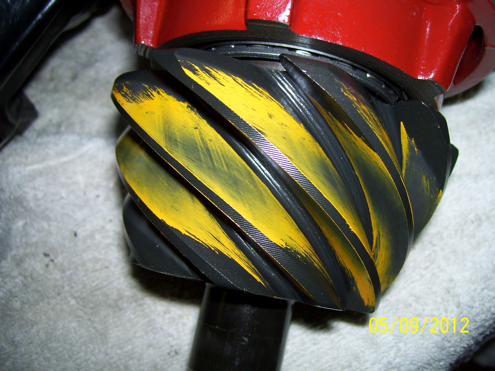
Most ring and pinion sets are shipped with a rust preventative coating on the gears.  This coating needs to be removed before installation to prevent any problems with gumming and to make sure you get accurate gear contact pattern representations when doing your final gear mesh checks using gear marking compound.  I like to use lacquer thinner to remove all of these oils before installing the ring and pinion gears.

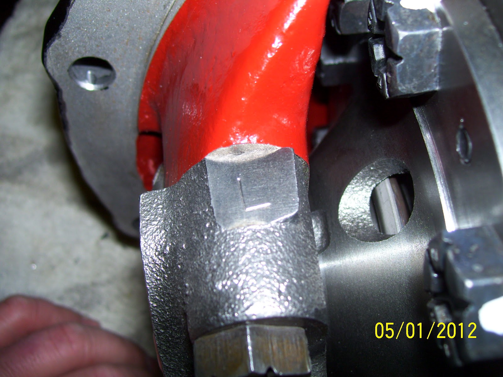
If you happen to be the first person to rebuild a particular 9-inch differential, chances are, the main caps will not be marked as to their proper location in the case.  Since these caps are machined to match the case, they cannot be mixed up (just like crankshaft main caps in an engine).  Therefore, it's a good idea to mark the caps before removing them to ensure they are returned to their proper location during rebuild.  In this shot, you can see this cap is marked with a large "L" to indicate this is the LEFT (or driver's side) main cap.

In similar fashion to the above photo, this cap is marked with a large "R" to indicate this is the RIGHT (or passenger's side) main cap.

Proper 9-inch case setup is not [possible without some accurate means of turning the bearing adjusters.  I made this simple pin spanner wrench out of some 1/4" flat stock and 5/16" rod and welded up two wrenches in a few minutes.  You could easily make something similar using a pair of 5/16" bolts if welding capabilities are unavailable.

Backlash settings are one area where the gear manufacturers specs must be followed to the letter.  Depending on the gear machining and finishing processes used by the manufacturer, the backlash targets can vary by several thousandths of an inch.  In my case, I chose a gear set from Motive Gear, who laps both the drive and coast faces of their gears during final manufacture.  This is rather unique and allows backlash targets to run slightly tighter than many factory and aftermarket gears.  My average backlash (measured at three locations around the gear) was set at 0.010".

While many gear manufacturers reference a measured pinion depth, it is rare that using this dimension alone will create the ideal pinion depth.  I have found the best option is to start with the pinion shim that came with the differential housing from the factory (if possible).  Nine times out of ten, this will nail the pinion depth on the nose.  Ford always references the "master case depth" specification in their pinion shim establishment, so using the same thickness pinion shim as installed from the factory is always the best place to start.

In this shot, you can clearly see an almost perfect gear pattern on the drive face of the gear.  The contact is perfectly centered from the toe to the heel of the tooth as well as from the root to the tip.  It doesn't get much better!

On the coast face of the gear, the pattern is again almost perfect.  The contact is biased slightly toward the toe (e.g., the inner diameter) of the gear tooth and is well centered from root to tip.

While not generally something that is referenced in gear pattern charts, the pinion contact should also be well centered over the entire tooth face, similar to the ring gear.  Here is the coast side faces showing a nicely centered pattern.

And here is the drive side faces showing excellent contact position as well.

Thursday, May 3, 2012

4-Link Bracket Update

When I last left off, I had the rear 4-link brackets positioned and tacked into place and had successfully mocked-up the housing in the car.  After several nights of measuring everything, I decided to fully weld the brackets into place and moved on to fitting the panhard rod bracket to the axle.

After a little bit of trimming and fitting and careful positioning of the bracket, I tacked it into place and verified the fit in the car.  As fortune would have it, the panhard rod fit very well and I could now weld everything fully.  With all of the axle brackets fully integrated into the axle housing, I headed back to the car for another fit test and attached everything one more time.  Again, I was very happy that everything looked to be in good order and I am now feeling a good bit more comfortable with the state of affairs in the rear suspension. 
There is still a lot left to do, but I am concentrating on getting the differential assembled and the axle housing outfitted with a new axle vent, right side brake line mount tab, left side distribution block mount, relocation of the brake hard line tabs and machine the integrated axle jack point / drain bung.  Once I get all of that squared away, I will prep the housing for powder coat, assemble and install the rear calipers, rotors and flexible brake lines and bend up the stainless hard line.  That should button up the axle assembly and allow me to concentrate on the rest of the rear suspension modifications (which will be fairly numerous).  Should be interesting when I’m done!

I don't think these brackets will fall off.  Once I had the 4-link brackets fully welded, I could concentrate on the panhard bracket.


After a few trial fits and tacking into place, I welded the panhard bracket in place.

Another look at the panhard bracket after welding.

With only a little clean-up, these welds will show nicely after powder coat.

Here is a shot of the left side brackets complete and mocked up in the car.
 
I just love how purposeful and "all-bidnez" this rear suspension looks under the car.

Looking toward the right side of the car, you can clearly see the panhard in place.

Thursday, April 26, 2012

Seat Sneak-Peek

Seats have to be one of the toughest things to choose for a hot rod muscle car.  Like custom wheels, it’s way too easy to pick a seat style that looks too “Ricky Racer” and fails to blend in with the interior of the car.  I like interiors that are “subtly modern” with styling cues that are easily identifiable to the original interior of the car.  For this reason, I have struggled to find a seat combination that looked nice, with a modern flair, but still kept some identifiable relationship to the original high-back bucket seats that were common in 69-70 Mustang interiors.

About a year or so ago, I saw few pictures of a 69 Camaro done out on the west coast that had a pair of seats that I thought might just do the trick.  Since the fellow who built the car was a friend of a friend, I asked second-hand, who made the seats he used.  I was shocked to learn they were seats taken from a 2011 Honda CRZ Hybrid!  Oh the humanity!

With this information in hand, I set about looking for a pair of seats to see how they might fare as candidates for my Boss 302.  After a year of searching, I found a pristine pair of seats locally (almost) for a fantastic price from a salvaged car with only 13 miles on it!  Score!

Once I got the seats home and started comparing the styling, dimensions and features to the old high-back buckets, I felt I had found the perfect seat option for my car.  If you can imagine the center panels in perforated black suede leather with the sides and headrest done in matte finish smooth black leather, you will quickly see how these seats will take on the appearance of a modernized Mustang high-back bucket.  After a bit of simple fabrication for seat mounts, these seats will bolt into the stock seat locations and should work fantastic!
Side by side, the Honda CRZ seat looks surprisingly similar to the original Mustang high-back bucket seat.  Proportions are very similar.  Hmmmm.....maybe a Boss 302 logo embroidered in the upper shoulder panel or headrest?

Without the often HUGE bolsters of many aftermarket seats, the Honda CRZ seat has very approachable styling that should work well with the 69-70 deluxe interior styling.........modernized of course.

Interestingly enough, the old high-back seat bottom is almost a full inch wider than the new seat.

Comparing the lower seat backs, you can see that there will be no concern for fit in this area.

Another look at the similarity in design of the old vs. new seat.  I'm lovin' this look!