Thursday, May 30, 2013

Street or Track Front Coilover Suspension Installation!

A major change of pace was a welcome thing this past few weeks as we reached a point that we could start some mechanical work to move things forward.  When I last left off, the plan was to spray the undercoating on the lower floor.  However, after careful consideration, we decided that it would be more beneficial to go ahead and fit the Street or Track coilover front suspension package (and the Unisteer rack & pinion steering kit) to the car to ensure everything fit and all required modifications could be made before the engine bay clean-up work came about.
As many readers of this blog are aware, I have had quite an issue with various “bolt-on” kits that are anything but.  As such, I went into the process of fitting the Street or Track front coilover suspension kit with A LOT of predisposition that the experience would come with a considerable measure of pain.  Even after repeated assurances from Shaun Burgess at Street or Track that these parts would fit an function as advertised,  I remained skeptical……
As an aside, I need to acknowledge Shaun for accommodating a special request I had when I ordered my kit.  Since the entire suspension on my car will be a specific, matte finish black powder coat, I asked that the majority of my kit components come without a finish of any kind to allow a much easier process of coating the parts in the appropriate color.  Normally, the kit components ship with a high gloss black powder coat finish, but in my case, Shaun set me up with most of the parts exactly as requested with only a few exceptions.  That’s service!
To begin the adventure, we started by turning the chassis around in the shop to keep the engine bay under good shop lighting and closer to the required tools.  Then, a careful review of the installation instructions allowed a comprehensive plan on installing the suspension components.  Fortunately, I was able to get a bit of a head start on the work in that I had already drilled the new upper control arm mounting holes a few months ago, using the nifty drilling template supplied in the coilover kit.  Then, the upper control arm assemblies were put together and test fit to the chassis in their revised locations.  This was the first indication that things were going to be different with this installation.  To my complete surprise, the control arms simply bolted in place with absolutely no struggle at all!  However, given my jaded nature, I wasn’t going to let one minor victory snatch us cleanly from the clutches of defeat.  Nope…….not me.
Next, the lower control arms were installed and these were basically a drop-in replacement for the production arms and no modifications were required.  One caveat was that I also installed the camber adjustment kits which eliminate the production eccentric adjustment bolts.  These too just bolted into place perfectly.
Next, the spindles were attached to both the upper and lower control arm assemblies and snugged up tight.  At this point, it was an irresistible temptation to cycle the assembly over the full range and marvel at the unbelievably smooth motion they allow.  Hmmmm……not bad.
Up next, the front strut rod assemblies were in the queue for installation, but first, the production sheet metal grommets had to be removed from the front strut rod chassis mount brackets to allow a solid seating surface for the forward strut rod mounts.  This is a simple operation that can be quickly accomplished with a small chisel and hammer to fold the edge of the grommet inward to allow it to be easily removed.  With these out of the way, the forward strut rod mounts simply index into the bracket holes and are secured by a large washer and lock nut.  Couldn’t be simpler.
Moving to the rear strut rod mounts, this operation was simplicity defined: Two bolts through the bottom of the lower control arm, through the strut rod flange and into the lower coilover mounts had the entire assembly secured and nicely complete.
Next came what would be the most involved part of the installation; the upper coilover mounts.  These are very nicely machined collars with the fabricated upper coilover mount on the bottom and a simple shock tower cover plate/reinforcement that attached to the top of the tower.
Since the top coilover mounts would need to be through-bolted to the top of the shock tower, each mount required three bolt holes to be drilled to allow the mounts to be properly attached.  To locate these holes, it is required that the shock tower braces (a.k.a. export braces) function as the drilling template for two of the three holes with the final hole position established by the top cover plate.  While it sounds a bit complicated to describe, the process is actually very simple and the work progresses very quickly once all of the parts are in place.
At this point, the “work” was basically done.  With all of the control arms in place and the upper coilover mounts secured to the shock towers, the pre-assembled coilover assemblies almost install themselves.  With spacers on each side of the spherical bearings in their proper location, the supplied retention bolts slipped cleanly through the brackets and in a matter of minutes, both coilover assemblies were in place and the Street or Track front coilover suspension kit installation was complete!  You read that right:  In about two hours’ time, the ENTIRE Street or Track front coilover suspension kit was fully installed.  I couldn’t believe it.  No skinned knuckles, no blood loss, no string of colorful expletives, and for the first time in this blogs’ history, a complex kit that truly lives up to its “Bolt-On” marketing statement.  It simply does not get any better!

After several months of work on the rear body sheet metal and roof, the time had finally come to swap ends of the car in the shop and start working on some mechanical things in the front suspension area.

A few months ago, I had the opportunity to drill the new upper control arm mounting bolt holes using the nifty drill template included with the coilover kit.  Here, I have test fitted the upper control arm pivot mount and you can see the original bolt holes above the mount.  These will be welded and smoothed at a later date.

The upper control arm assembly is installed first.  This was my first indication that the Street or Track coilover suspension kit was a going to be an absolute joy to install.  This control arm bolted up in mere minutes with absolutely no issue.

Street or Track includes these very high quality screw-in ball joints in the coilover kit.  These joints make assembly and future service a breeze.

Another sign of quality is the heavy duty spherical rod ends used on the inner control arm pivots and the grade 8 fasteners.

Notice the ample clearance and clean look of the Street or Track components.

With the lower control arm installed and the spindle connected, the suspension is starting to take shape and look exceptionally nice, even in bare steel.

With the upper and lower control arms installed and the spindle connecting them, the system articulates over the full range of motion with amazing smoothness.  Just a couple of fingers are all that is required to cycle the assembly in this state.

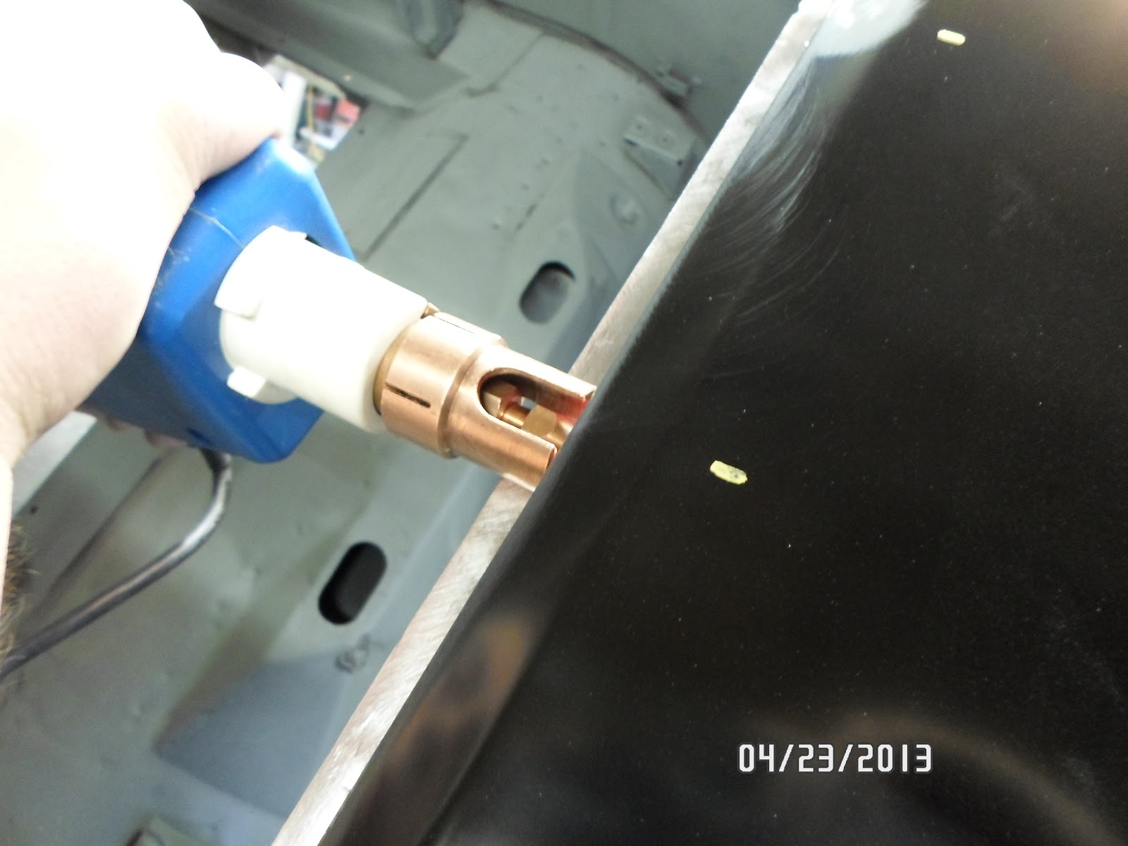
Removing the factory strut rod sheet metal grommet is easily accomplished using a small cold chisel and hammer.  By folding the grommet toward the center of the mounting hole, it can be easily removed without damaging the surrounding bracket.

The Street or Track adjustable strut rod forward mounts index into the mounting bracket and are easily tightened from the front.  In this view, the spherical rod end can be seen in the proper position to allow maximum suspension travel without binding.

The rear mount of the strut rod is sandwiched between the lower control arm and the lower coilover mounting bracket and is secured by two bolts installed from the bottom.  The result is a very strong and sanitary assembly.

As ugly as the original export braces are, they come in quite handy in locating the mounting holes that require drilling in order to properly mount the upper coilover mounting brackets.

The upper coilover mount is bolted into place with three bolts, creating a very solid upper mounting structure for the coilover.

The top of the shock tower is finished off with this tidy capping plate that prevents damage to the upper shock tower flanges when tightening the mounting bolts to spec.

The finished coilover installation is a thing of mechanical beauty.  Everything on this kit fit to perfection and the entire system is exceptionally serviceable and well made.  I am truly impressed!

A look at the completed installation on the right side of the car.  When all of the components are finished in their final matte black powder coat, the system will look extremely clean and sophisticated.  Can't wait!

Friday, May 10, 2013

Replacing the Roof Skin – Part 4 & DONE!

Another solid week of progress is in the books and I am happy to report the new roof skin installation is complete!  With the interior surfaces primed and dry, work shifted immediately to the top side work.  The goal in this phase of the build is not to apply finish body filler, but to seal and generally level the roof seams and remove the EDP coating on the panel in preparation for a solid foundation of DP40LF epoxy primer.
We began with filling the formerly leaded roof seams with All-Metal repair compound from US Chemical.  All-Metal is a heavy-bodied, metalized polyester filler that is excellent for replacing lead in such applications.  Unlike lead, the surfaces prepared for All-Metal require no tinning or acidic preparations to condition the surfaces for filling.  Instead, standard body filler preparations (e.g., grinding to clean, bare metal with 80-grit abrasives and solvent cleaning) are all that is required to ensure a secure and waterproof bond to the parent metal and there are no concerns downstream of incompatibility with the finishing and paint system products to come.  Application is exactly like any standard body filler and All-Metal can be shaved with Surform (a.k.a. cheese grater) tools in the same way you would standard body filler as well.  However, once it sets, All-Metal is a pain to sand and loads up sandpaper like a beast.  That is a major reason that I use it as a bulk filler on seams, etc., and follow it up with Rage Gold for all finish work.
With the leaded seams filled to just below surface level, the process of removing the EDP coating from the roof skin was begun.  This was mostly accomplished with the DA sander and amounts to slow tedious work.  In the end, we ended up finishing the last half of the job with aircraft paint stripper sparingly applied and simply used a straight edge razor blade to peel the DP off in long ribbons.  Probably cut the process time by 75%.  When Ted saw me do this……..he was NOT impressed!  I told him he needed the DA practice.  Haven’t seen him in a week……(kidding).
With all of the EDP removed, the entire bare metal surface was sanded with 80-grit to provide proper “tooth” for the primer and the entire surface was then blow off with shop air and generously swabbed with wax and grease remover.  Then a thorough wipe down with a fresh tack rag, followed by a final cleaning with wax and grease remover and the roof skin was ready for primer.
After mixing up a fresh batch of PPG DP40LF epoxy primer in my 3oz touch-up gun, I started by cutting in the A-pillars, window flanges  and drip rail channels to ensure they were coated well and completely.  This also makes shooting the flatter surfaces much easier as you don’t have to worry about getting enough primer on any of these oddball surfaces at the same time you’re trying to cover the larger areas.
I applied two solid coats to the cut-in areas and let each coat flash off for a solid 20 minutes to avoid any issues with solvent pop, etc.  Then I switched over to the flat areas of the roof and applied two coats of DP to those surfaces as well, making sure to blend over into the cut-in flange areas well to avoid any separation lines in the final coat.  I tried to apply each coat slowly and deliberately to ensure it covered well and lay flat and smooth.  I admit to taking a few opportunities to tinker with air cap settings at the same time and was quite satisfied with the final coat as a result.
With that, the roof skin replacement is now complete and the next phase of work will once again take an interesting turn.  I am happy to say the entire tub is now rust free and solid in every way and the work on the horizon will soon transition to more construction than re-construction.  Next up is lining the bottom of the car with U-POL Raptor Liner and then into the engine bay for a lot of clean-up and smoothing work.  Should be fun!

All-Metal is used to fill the formerly lead-filled seams at each corner of the roof.  It is leveled to just below the surface contour to allow final finishing with Rage Gold.

Front A-pillar filled with All-Metal

Ted getting started on the removal of the EDP coating using the DA.

The sanding process proved to be painfully slow.  Soon after I shot this picture, I switched over to aircraft stripper and a razor blade and the process started flying.

After all of the EDP was removed, we swabbed everything down with wax and grease remover.

After tacking off and cleaning a second time with wax and grease remover, the new roof was ready for primer.

I started priming all of the window opening flanges and drip rail channels to ensure full coverage.

Cutting in the complex areas of the roof makes spraying the larger, flat surfaces much easier since you don't have to worry about missing spots in the more intricate areas.

Another shot of the rear window flange corner after cutting in with primer.

With the second coat still tacky, the new roof looks awesome!

After 24 hours of dry time, the new roof skin looks better than new and I am able to take in the full measure of satisfaction knowing that replacing the roof skin was absolutely the right thing to do.
 

Friday, May 3, 2013

Replacing the Roof Skin – Part 3

Spring has FINALLY sprung here in Michigan and other than several days of rain (which is needed); we have not let a lot of grass grow under our feet in the past several days.  The bottom line, in fact, is that the Boss has a new roof skin installed and it looks absolutely fantastic!  The installation went precisely to plan and the finished product fits arguably better than the original roof.  Giving credit where it is due, I can thank Tony D. Branda Performance and Dynacorn for a great-fitting roof skin delivered to my door in flawless condition.  That helps get things off to a good start no matter what you’re working on!

When we last left off, the interior bracing structures were primed and it was time to start the final fitting of the roof skin in preparation for welding it permanently into place.  One area in particular that required a bit of extra grey matter stirring was how best to weld along the drip rails without trashing the solid, original drip rails in the process.  These are very thin gage metal and welding to them can be quite a challenge.  In addition, the flanges along these rails are very narrow and would only allow a 3/16” plug weld hole to be used.  And finally, there are about 45 welds along each rail!

However, the first order of business was to drill and/or punch all of the plug weld holes in the roof skin flanges and then transfer their locations to the main body structure so the weld surfaces could be properly prepared.  Then, a set of small c-clamps were modified to help in clamping each drip rail tightly for ease of welding.  With all of our clamping devices set to go, we trial fit the roof skin one last time to ensure everything was exactly where it needed to be, and made any necessary adjustments to ensure the fit was a perfect as we could get it.
With the roof skin ready to go, it was time to work out the drip rail welding situation.  Since the drip rails present a welding condition not covered by “normal” textbook welder settings and setup, I decided the best thing to do was crate a test panel that precisely duplicated the materials and plug weld configuration that I would encounter on each drip rail.  I drilled a series of plug weld holes at the same spacing as those on the drip rails and set the welder up using the recommended settings for the material thickness as a starting point.  In addition, I switched to my tapered MIG gun nozzle to allow better access to the narrow rail recess and to allow me better line-of-sight observation of the weld arc area itself.

I began testing various welder settings to determine what gave me the best penetration and flattest weld with the most minimal heat affected zone.  What I ended up with was a wire speed close to the recommended setting on the chart, a wire stick-out of about 3/8”, and a heat range quite a bit hotter than you would normally expect.  In the case of my Lincoln 180C welder, I set the machine up at 35CFH gas flow, and a wire speed of 3 and heat range of E.5.  This allowed the weld to penetrate quite completely and fill the plug weld hole fully without creating a heap of extra metal that would have to be ground away. The heat affected zone was quite compact as the weld required very little “on” time to complete the job.  With this confidence in the weld process established, the process of actually welding in the roof skin was just about as textbook as it could have been.  We tacked down the corners of the roof and the center of each drip rail and started the methodical skip-tack technique around the perimeter until the entire roof was fully welded into place.  And I am happy to report the spot weld settings and technique developed on the test piece worked perfectly to secure each drip rail.
The following few evenings were spent grinding each plug weld smooth and finishing the roof flanges.  Next, the location of each trim rivet was sanded clean to make for an optimum surface to weld them in place.  Pretty quickly, we encountered another small snag with regard to a welding tool deficiency.  In this case, my Motor Guard pin welder could not properly reach over the window flanges to weld the trim rivets in place at the proper location.  However, a quick bit of internet investigation revealed the proper extension kit that would remedy this issue (or so I thought).  So like any dedicated enthusiast, I order said extension kit and a few days later discovered the gift of UPS had once again graced my door with “stuff”.

Once the extension kit arrived, I quickly discovered the length was going to work, but the “flats” machined in each side of the grounding collar were not going to allow the trim rivets to be welded at the proper 5/16” height above the flanges that were required on the Mustang.  So, off to the mill I went to machine the collar flats a bit deeper to allow me to very easily align the trim rivets at exactly the right height to be welded to the roof flanges just like the factory did.  Once the modifications to the collar were made, the process of welding on the trim rivets took all of about 15 minutes, with every rivet positioned at exactly 5/16” above the flanges just like the original.  After a quick dusting with the nylon cup brush to remove any fuzz from each rivet, the job of attaching the new roof was now complete.
Next up, Ted and I moved directly to preparing the underside areas of the roof and drip rail flanges that were affected by the welding heat and scuffed the entire interior surfaces of the roof and braces in preparation for a fresh coat of DP40LF primer to seal everything up.  Fortunately, the largest volume of sanding could be done with careful application of the DA sander with some 120 grit sand paper and the rest of the details were scuffed by hand or with the nylon abrasive cup brush.

After a good swabbing with wax and grease remover and a few thorough applications of the tack rag, we mixed up a batch of primer and cut-in the detail areas.  Once the cut-in primer had flashed off for several minutes, we applied two medium-wet coats of primer-sealer and let the works dry overnight before rolling the car back upright to start the next phase of the roof installation which will include preparing and filling the large seams at the A and C pillars and applying a few coats of epoxy primer. 

With such a narrow flange on the drip rails, we were only able to use 3/16 plug weld holes along the flange.  In this shot, we have transferred the locations of each weld to the flange underneath using our trusty paint pen.  Once the roof skin is removed, these marks will be scuffed to bare metal for welding.

Nice tight flange fit with no clamps is an excellent sign that this new roof skin is as good as they come.

I modified these inexpensive mini c-clamps to clamp along the drip rail channels.  At $1.84 each, this was money well spent to get good clamping without damage to the drip rail or flange.

Ted checks the fit on the rear corners after clamping.  Note the number of clamps used along the drip rail.

All plug weld surfaces are sanded to bare metal and ready to go.

Drip rail channels have been scuffed to bare metal and prepped for welding.

With all fitting work complete and the roof skin clamped into place for the final time, the results look excellent.  Arguably, the fit of the new roof skin is better than the original that came off.

One major issue that needed to be resolved was how to set the welder such that the small plug welds would fully penetrate as well as fill the plug weld hole without burning through or heaving a huge amount of material on top of the weld that we didn't need.  The solution was this simple test assembly that allowed each setting to be dialed in perfectly before crunch time.

These were the weld trials after a few adjustments.  Note the significant differences in heat affected zone and weld bead size that results from very small adjustments to the wire feed and amperage.  For reference, the weld at the far left was the final set point.

The first weld settings based on the recommended setting chart included with the Lincoln 180C welder created welds a bit too cold with too much material deposited.  However, these early tests showed how sensitive this type of plug weld is to small changes in welder setup.

This tapered nozzle was required to get close enough to the weld surface.  Also, the weld wire stick-out was ideal at about 3/8" from the MIG tip.  Combined with a wire speed of 3 and an amp setting of E.5, this created the perfect weld in the small 3/16" plug weld holes with excellent penetration.


This is a great shot of how nicely the drip rail welds came out.  Each weld had 100% penetration with minimal crown and absolutely no porosity.

Welds along the rear window opening flange were very conventional 5/16" plug welds.  Conveniently, the same settings used on the drip rail plug welds worked well here also.

Welds along the front windshield flange were very straight-forward as well.


Here is a good look at the weld penetration we achieved along the bottom of the drip rails.  100% penetration everywhere.  It doesn't get much better.

Welds at the front A-pillar joint include a small seam along the lower edge.

Fully welded!  With the clamps removed, we get the first look at the profile of the car with its new roof.

All of the welds were brushed with a nylon abrasive wheel and the flange edges were trimmed before the welds were ground smooth.

After grinding the drip rail welds, the result was quite acceptable.

Window flanges were smoothed and the A-pillar corners were cleaned up as well.

I had to modify the flats on the Motor Guard extension kit to allow it to properly position the trim rivets at the correct distance above the window flanges

This is what a proper trim rivet looks like.  In my opinion, this is a far better option than the "repair" screws that are often used.

There is a small magnet in the tip of the electrode that holds the trim rivet head securely while it is being positioned on the surface for welding.

With the trim rivet in place in the electrode, the stem protrudes above the tip by only a small amount as shown.

Here is an idea of what the whole (modified) works looks like at the moment the weld is created.  Sorry it's not a better shot.......

And there you have it!  A nicely welded trim rivet in the proper location.  Once the process was started, the entire job of welding trim rivets to the front and back window flanges took less than 1/2 hour.

Much of the sanding of the underside of the roof was easily accomplished with a DA sander since there was no cross bracing in the way.

The cross brace details were sanded by hand.

Two medium-wet coats of PPG DP40LF epoxy primer has the interior roof and bracing looking very nice and protected better than they ever were from the factory.

Primer coverage between the braces and the roof skin is very good as a result of cutting in these areas at the beginning of the priming process.

Coverage of the primer was good even in the deeper cavities of the B-pillar bracing.

The finished interior surfaces of the new roof look beautiful in a fresh coat of PPG epoxy primer.