Sunday, April 1, 2012

Axles and Brackets & Welding – Oh my! - Lots of little projects crammed into a few weeks

Now that most of the major chassis work is done, there has been a bit of a “phase shift” in working on my car and it’s taken me a bit of time to get used to.  In short, I got a little spoiled with the “visual” reward I got when making large panel replacement progress because it simply looked like I was making big progress.  In the past few weeks, I have accomplished a lot of small things that add up, but I found myself struggling with feeling like I was underachieving on all these smaller jobs because the visual impact just wasn’t what I was used to after the past two years.  But, as I have conditioned myself to do, I put my head down and kept moving and pretty soon………more progress.  I like that!

When I last left off, I had to complete the front trunk floor seam by fully welding it along the bottom of the car and grinding all that work smooth for priming a filling later on.  In addition, I added the front corner reinforcements and the rear bumper brackets to round out the repairs at the back of the car.  Fortunately, all of this work was quite uneventful as everything had pretty much been nailed down in the earlier work such that this remaining work practically fell into place.  As a final test (and a bit of personal entertainment), I test fit the upper coilover mount in place and was happy to see it lined up perfectly and will do a good job hiding any sign of the weld seem in the axle tunnel area that may try to give itself away.
My next short project was to make some small repairs to my axle housing, tidy up the 9-inch differential housing and get the new Moser 31-spline axles ready for battle.

Quite some time ago, I identified some small cracks at the spring perch welds on the axle housing no doubt caused by past abuse.  After cutting of the spring perches in preparation for the installation of the Heidts 4-link brackets, the time was right to weld up these flaws along with filling a few weld gouges left behind so that the axle tubes would be in good shape for the new brackets.  With these repairs out of the way, I can now concentrate on getting the 4-link brackets mocked up, welded and finished in time for the weather here to warm up enough to allow me to sand blast the completed housing in preparation for powder coating.
Once I had the housing in shape, I shifted focus to the 9-inch differential case restoration.  In the past few months I spent a good bit of time “decoding” the differential in my car.  While I knew the housing was original, I also knew the differential case was not.  Originally, my car came with a 4.30 Detroit Locker diff, however when I purchased the car, the diff it came with was a measly 3.50 open 31-spline crapper.  As luck would have it, the housing itself was the genuine article:  A nodular iron case with a rare Daytona pinion support intact and in fantastic condition.

Confident that I was working with something worthy, I stripped the differential completely and deburred everything to remove all of the clag and sharp edges.  I soaked the parts in Purple Power liquid cleaner to remove all traces of the original red oxide coating on the unit and ran it through the blast cabinet to clean the more stubborn soil off the parts.  Then, everything spent a few days soaking in a nice, fresh chelant bath using Esprit Performance’s new chelant offering that does not include metal cleaners.  As I have become so accustomed to over the past year, this stuff kicks major butt!  Every piece of the differential (and a lot more pieces I will report on at a later time) came out perfectly free of rust with absolutely no elbow grease.  The part condition was so good in fact, that I simply dried the parts off and went straight to powder coating with no hassles whatsoever.

After I had applied a fresh coating of satin black urethane powder on all of the diff pieces, I shifted focus to the interior surfaces.  To coat and protect these surfaces, I turned to a venerable coating know far and wide in performance circles.  The product is called Glyptal and is an offshoot of General Electric.  The proper name for the paint is #1201 Red Enamel (insulating paint), but its original purpose was an armature paint for industrial electric motors.  Over the decades, its uses have expanded considerably, even to include the interiors of many performance and racing engines.  I have never condoned painting the interior surfaces of any machine using a pressurized lubrication system, but in cases where the machine is splash oiled, like a differential or perhaps a Model T engine, then Glyptal is a fine candidate.  The product does an excellent job sealing the casting to prevent residual core sand and rust from soiling the lube and to provide a nice slippery surface to keep the lube in the sump where it can do its job.  A few coats of Glyptal, applied by brush and cured at 250 degrees F for two hours leaves a finish that is surprisingly durable and looks remarkably good.

As I complete this installment, I have my rear Cobra calipers and front pinion support baking in the powder oven with a close eye on the door for Summit Racing to deliver the one lone pinion bearing I need to start putting the restored differential together.  Timken roller bearings throughout.  Should be as close to bulletproof as I can make it.  Also, I plan to mock up the rear axle housing and 4-link suspension in the car to allow me to weld up the rear brackets in place and prep everything for sand blasting and powder. Once that is complete, I will finish assembling the rear axle assembly and put it away until the time comes to put it in there for good.

The lower seam of the forward trunk floor patch was finally welded in.  Short stitches of about 1" long were staggered across the seam to minimize warping.

With the welding complete, I could feel confident that the repair was sturdy and grinding could begin.

Here is a close-up of the top side of the weld seam showing complete penetration of the weld.

The trunk floor seam from the top.  This will all be invisible once the Dynamat material is installed.

After grinding all of the welds on the bottom of the repair, I was pleased that everything looked like it require little filler to smooth things out.

I finished the trunk floor repair by adding the corner brackets to duplicate the original feature.

As a test, I test fit the upper coilover mounting bracket and found that this will work well to hide any imperfections in the joint.

Bumper bracket alignment was very good right out of the box.  This is the left rear bumper bracket after final welding and a pass with the angle grinder to clean things up.

Here is the left rear bumper bracket from the inside.

The right rear bumper bracket alignment was also very good straight off.

Right rear bumper bracket inside view.

After cutting off the original leaf spring brackets, I found weld gouges and a few small cracks that needed to be repaired before moving on with other modifications.

Here is a better view of the areas requiring weld repair.

I dialed up my trusty MIG welder and filled the u-bolt chaffing scars on the housing along with the small cracks and weld gouges.

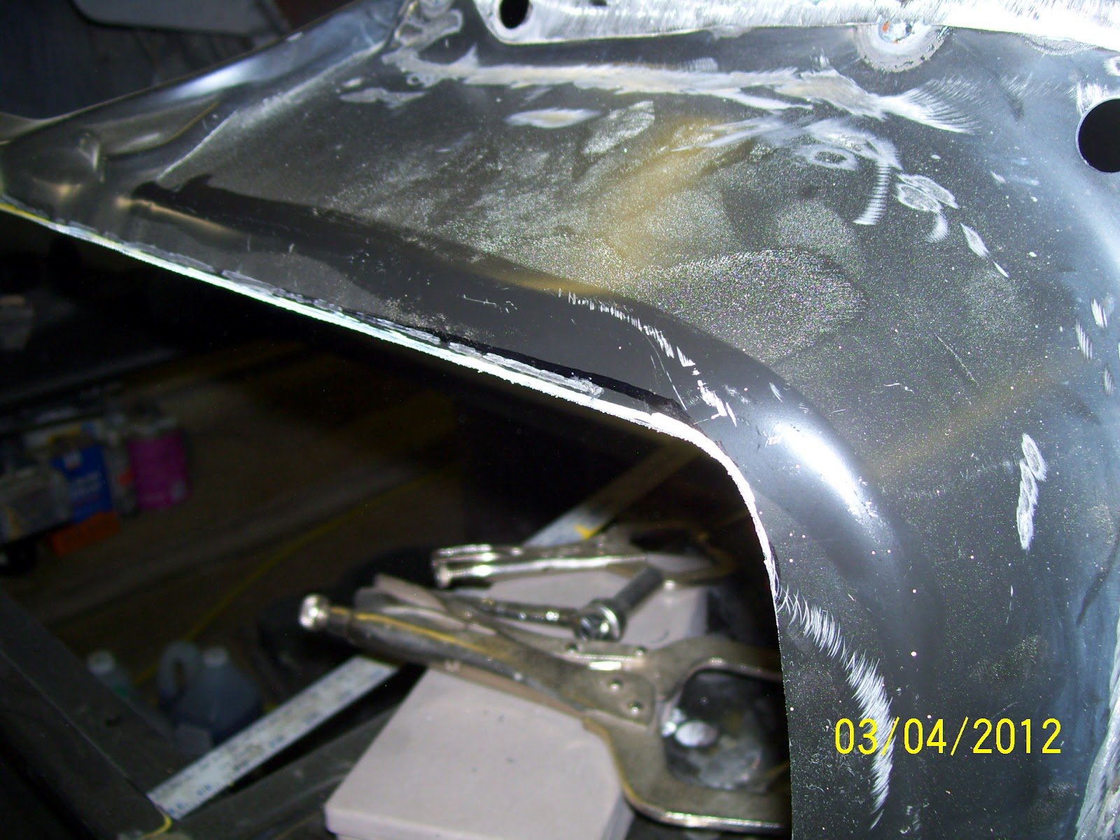
A few minutes with the angle grinder and the welds were smoothed up and the evidence of any prior damage was now gone.

After powder coating the axle bearing retainer plates and installing new wheel studs in the Moser 31-spline axles, I pressed new bearings and lock rings on each axle.

The finished assembly looks all-business.  Note the o-ring seal around the O.D. of the axle bearing.  This eliminates the need for axles seals in the housing.

Decoding my rear differential case revealed a genuine nodular iron unit.

The interior of the differential was actually in surprisingly good shape.  Note the factory red oxide paint on the interior surfaces.

Another bonus!  This is a very desirable but rare "Daytona" pinion support.  Other than the casting number, Daytona pinion supports are identified by the very large rear pinion bearings used as opposed to the identically sized (small) bearings used on the front and rear of the pinion in a "standard" 9-inch.

After stripping the factory paint and scrubbing the red oxide paint off in a bath of Purple Power degreaser, I ran the parts through my blast cabinet and then deburred all the sharp edges with my die grinder.

Inside the case, I ground down all of the casting flash and sharp edges.

In preparation for coating, I soaked all of the differential parts in Esprit Performance Rust Remover, my favorite and extremely effective chelation rust remover chemical.  Magic stuff.

Since chelant is 80% water, I cover the tub with a trash bag and a piece of panelling to reduce the evaporation rate.

With little more prep work than drying the part off straight out of the chelant, I applied my favorite semi-gloss urethane powder coating to the diff case and cured it up.  This is a shot straight from the oven and the part is still too hot to touch when I snapped this photo.

The pinion yoke looks great in fresh powder.

With the powder work complete, I prepared the inside surfaces of the diff case for a couple of coats of Glyptal #1201.

Using nothing more than a simple 1" brush, I painted all of the inside surfaces with Glyptal to seal everything up.  A second coat was applied a day later.

Another shot of the fresh Glyptal coating from the pinion nose area.

Once the Glyptal coating is dry, it's hard to believe it was applied by brush.  No brush strokes visible anywhere!

A look inside the case just before oven curing @ 250 degrees F for two hours.

Here is the case right from the oven.  The Glyptal got a bit darker and slightly more glossy after curing.

A look inside the pinion nose are and the Glyptal looks great.

Sunday, March 11, 2012

Tail Light Panel and Trunk Floor – Part 11: Tail Light Panel Install Complete

Today was a GOOD day!  When the fall and winter season began, I had a pretty tight plan on what I thought I could accomplish before the Spring and I am very happy to report, that it appears that plan will work to perfection.  With the installation of the rear tail light panel, I am happy to say the major structural repairs to my car are complete.  I still have to complete the welding on the axle tunnel repair panel seams and get the new panels in primer, but at least I have the comfort in knowing the car is structurally sound once again.
Several weeks ago, my Dad and I raided my local NPD for a truckload (literally) of sheet metal that included a new tail light panel and trunk lock support bracket to complete my panel replacement at the rear of the car.  The tail light panel was a very nicely detailed stamping that fit the car quite well.  The trunk latch support on the other hand was less so and required a bit more tweaking to get in order.  Nothing major, just tweaking.
I started the installation by carefully centering and squaring the new trunk lock support on the inboard tail light panel.  I have seen a lot of variability in the location of these brackets over the years, but it is critical that this be well centered so that the trunk lock mechanism works smoothly and the fuel filler tube passes through without interference, so take your time and get this right.
With the lock support welded in, I was finally to the point I could start the final fit of the tail light panel.  The first thing I did was to establish the center of the rear trunk floor aperture and I did the same on the tail light panel lower interior flange.  I reasoned that if my preparatory work was accurate, these two lines would line up when the panel was in its optimum position.  This idea was a good one as alignment was easily verified with these reference points and positional repeatability was spot-on.
The first observation during the panel mock-up was that both quarter panel end cap flanges overlapped the upper raised panel bead on the tail light panel significantly.  This prevented the panel from seating on its end-flanges properly and generally looked unfinished.  So out came my trusty paint pen and straight edge and I marked the appropriate trim lines that would allow the panels to mate correctly.
With the end cap flanges trimmed, the panel fit amazingly well.  This allowed me to install Clecos in the four corners with confidence and clamp the flanges with welding clamps such that I could accurately locate the spot weld locations around the panel.  Once this operation was complete, I punched the required plug weld holes with my pneumatic punch and drilled the few remaining holes I couldn’t reach with the punch.  After a little deburring of the drilled holes, I fit the panel once again to verify everything was looking flight-ready.
The actual welding of the panel went smooth and without drama.  I started by locking down the corners where I had the clamps located and then moved around the panel, welding the spots between the clamps to ensure tight flange fit and little distortion.  After about an hour of welding and cooling each spot with air, the panel was fully installed and the chassis was solid once again.
I still need to weld in the bumper brackets, complete the axle tunnel welds, trim the drip edge at the front edge of the trunk floor, and prime the whole area, but those are small jobs that will be made much easier now that the car can be rolled over in the rotisserie again without concern for the integrity of the structure.  It was a very good day…….

The tail light panel; installation was preceded by having to align and weld in the trunk latch support to the panel.  This is much easier than trying to do this with the panel tacked into the car.

The first mock-up of the tail light panel shows the fit was remarkably good.  Only slight tweaks would be required to get it right.

I was amazed at the fit at the lower rear of the trunk floor in the unclamped state!  Couldn't ask for better.

Here, you can see the overlap of the end cap over the upper character bead on the tail light panel.  This wouldn't allow the panel to register fully against the end cap flange as evidenced by the gap in the upper corner of the end cap.  This will need to be trimmed and hand fit to work properly.

Exact same overlap condition existed on the right side of the tail light panel as well.

Using my trusty paint marker and a straight edge, I marked the end cap flange where I needed to trim it back to fit.

Here is the right side marked for trimming as well.

With the tail light panel removed it is much easier to see the extent of trimming required on the left end cap flange.

The right side end cap flange required just a little bit more trimming for proper fit.

Left side end cap is trimmed and ready to go!

Right side end cap also ready.

Now you can see how consistent the panel bead reveal is and the corner fit is much tighter.

Right side fit is also very nice.

After marking and punching the spot weld holes in the end cap flanges, I clamped the tail light panel in place and located it with Clecos

This is a slightly better shot of how I mark the weld location on the tail light panel flange for sanding later.

Welded!  This panel went in like butter and the flange fits were superb!

Right side shot of the panel welded into place.

A shot along the bottom edge of the tail light panel flange.

Left side end cap area after a bit of metal finishing.

Right side end cap area after metal finishing.

Only a spot of high-build primer will be required to smooth this flange area.

After welding, the trunk floor to tail light panel interface still looks tight and right.

Another shot down the lower flange to show how straight everything turned out.

I just HAD to throw the end caps, trunk lid and some old tail light bezels in place to see how it looked!  Awesome!

It's been a LONG time since this 'ol girl looked so "complete" in the posterior.  A good day indeed!

Thursday, March 8, 2012

Hydraulic Clutch Master Cylinder Work

I have to begin by apologizing for the poor photographic account of this latest work as I had a minor camera glitch (actually operator error) that prevented me from capturing some early “set-up” and template making shots, but hopefully you’ll get the idea.

A long time ago, I decided that a mechanical clutch linkage was not going to fulfill the design intent I had in mind for my car.  The factory 70 Mustang clutch “Z-Bar” linkage intrudes heavily on the under hood space where you’d rather put headers and generally clutters up that corner of the engine bay.  After a lot of research, I decided I liked the look of the latest generation of hydraulic clutch kits from Modern Driveline.

Since my plan is to run a “Z-spec” T5 transmission and late model Fox body Mustang bell housing, clutch, 157-tooth flywheel and mini-starter, I wanted something that was simple and easy to install.  Generally speaking, I seem to have gotten that in this kit.
Knowing ahead of time that Mustang firewalls are all over the map as far as hole stamping locations are concerned, I was prepared to have to do some tweaking to the parts to make them fit as I had intended.  As such, when I began to trial fit the clutch master cylinder mounting flange to the inboard side of the firewall, I knew right away what measures would be required to make it fit properly.  So out came the template paper and off I went.

The flange, as it is shipped, is a symmetrical shape, but I quickly learned that to fit my specific car, I would need to trim and contour the right side edge of the mounting flange to work with the stamping contours of the firewall.  My mission was to do nothing more than drill the required mounting holes and as luck would have it, I was able to meet that goal with very careful positioning of the flange.
With the mounting flange modified and fitting the firewall well, I moved to the outboard side of the firewall and with the help of my Dad, was able to secure the mount into place to verify the fit of the master cylinder and the original booster.  Fortunately, the Wilwood master cylinder bolted right up to the base adapter and the factory booster popped right into place with absolutely no interference whatsoever.  The fit is snug, but extremely clean and tidy.  Coupled with the rack and pinion steering and a restored booster, this area of the engine bay should be very clean and functional with a look that defies the observer to recognize it as anything but stock.  So far……I love it!

Here is the modified Modern Driveline hydraulic clutch master cylinder mount in place.  The mount comes as a symmetrically profiled part, but I was pretty sure that wasn't going to work out of the box on my car.  I was right, but the correction was easy with an accurate template and a few minutes with the grinder.

Here is the firewall mount for the master cylinder.  The original clutch rod hole is intact and unmodified although the new master cylinder hole location is to the far right of the original (larger) clutch rod hole in this shot.

Here is the Wilwood master cylinder mocked up on the new mount.  Cleeeeeeeeean!

Here is the view of the new master cylinder and pushrod from the "business end".

The clearance to the original vacuum booster is quite adequate even though this shot makes it look rather close.

This view give a much better idea of how much clearance there actually is.  I think I'm going to like this!