One of my biggest concerns while tackling the cowl replacement was an area in the driver side kick panel wall that was completely rusted away as a result of a large amount of debris that was trapped in the cowl box and allowed water to collect and rust the area away. As soon as I was able to properly survey the damage, I set off to finding a replacement panel or patch for the area, fully expecting that something would be available from Dynacorn given they offer complete 69-70 bodies. I scoured every Mustang parts supplier catalog I have and found absolutely nothing available. At this point, I figured it probably a case that the part was too new and was just a phone call away. Yeah……right. No joy on that idea no matter where I turned. So with my hope waning, I gave Dynacorn a call for the straight skinny directly from the source. Yep…….another disappointment. The word I got from the gentleman I spoke to was that Dynacorn withholds certain parts to maintain exclusivity for a period of time (a moratorium of sorts) and that there were no immediate plans to offer the inner kick panel as a replacement part. So, with that disappointing thread of information set deeply in my brain, I set out to see what was available in the used parts market.
After several days of phone calls and emails with most of the major used mustang/classic car parts yards around the country, I simply couldn’t justify the cost of buying a used part cut out of a wreck when the total cost to my door would start approaching the cost of a new floor! So naturally, I did the only thing left to do: make my own panel die and hand-form a patch.
I will have to admit up front, I really wanted to avoid making a patch from scratch. Not because it is beyond my capabilities, but because I really don’t like my MIG welder for doing delicate work. In fact, it really sucks and at some point I will replace it with a Miller when the means to do so arrive. But, I have to dance with the date that I came with, and suffer through it as best I can.
The first task involved in this repair was to make several cardboard and Mylar patterns of the kick panel opening to allow accurate layout of the profiles. These templates must be as accurate as possible and they must be able to be indexed to the body so that their absolute position can be established every time they are transferred from the body to the work and back. I have to give the template credit to my dad as he is an absolute soldier on these things while I’m away at work or generally jerking around doing something else. Thanks Dad!
Once the templates were made and the fit verified, I transferred the marks I used to define the general repair area on the kick panel to the templates so I knew exactly what area to duplicate in the repair die. Then, after some rummaging through the scrap steel bin, I gathered up the material necessary to fabricate a forming die that I could use to accurately fabricate a decent patch panel. I decided to use a piece of ½” steel plate as the base for the forming die as I knew I would be hammering on it quite a bit and needed a good solid base to work with. The remainder of the die was fabricated from ¼” hot rolled steel strap as this duplicated the step in the panel perfectly. Using the cardboard and Mylar templates, I transferred the proper contours to the steel and set off to grinding, filing and sanding them to match the shape exactly.
Once satisfied we had the contours correct, I welded the step forms to the base plate using the templates to verify alignment then ground the welds smooth and polished them with a flap wheel to remove any burs and smooth the surface. At this point, I could now reproduce the inner curvature of the patch to allow a lip to be formed that would duplicate the detail of the original panel, so back to the templates we go. Once the curvature was established and transferred to the metal, I carefully cut out the rough shape with my flame wrench (a.k.a. my oxy/acetylene cutting torch) and finished the surface on the grinder, belt sander and flap wheel. I completed the die by gently rounding all of the inside corners to reproduce the proper bend radii and de-burred everything once more with the flap wheel.
Satisfied I had a good forming die to work with, I cut a piece of 20 gauge galvannealed steel I had in my stock to be slightly larger than the shape I required and clamped it into the die. Galvannealed steel is a rather specialized sheet metal material that is coated in a durable form of galvanizing for great corrosion resistance and is annealed to allow it to be formed and shaped with tools rather easily. Some of the higher-end restoration supply houses still carry it, but specialty metals suppliers around the ‘net show it available in small quantities as well. It’s good stuff and I highly recommend it for this type of work. Of course, plain annealed mild steel will work equally well, but will lack the extra corrosion protection.
While the tools required to do this type of work are relatively simple, it is common to have to make a tool to do a certain job or achieve a certain shape, and this job was no exception. Fortunately, I have another little restoration secret I’ll pass along to anyone who finds themselves in a similar situation. Often times, you will need to make a forming tool that needs to be struck with a hammer to get the results you need. However, you must be very careful to not assume just any old steel is suitable for the task, as striking many types of steel with a hammer can often result in splintering or fracturing of the tool resulting in very dangerous flying debris. Fortunately, there is an inexpensive and plentiful supply of form tool “blanks” available right from your home improvement store in the form of masonry chisels. That’s right, those oddball chisels used to split bricks and concrete make excellent and very customizable forming tools at very low cost. These chisels are designed for heavy striking forces and are almost always made of good quality forged steel. Try to stick with the US-made tools as they are usually of much higher quality than the less expensive import competitors. Often, these tools have a very broad range of widths allowing you to create almost any shape you need for complex forming jobs. In my case, I cut back a 2” wide flat masonry chisel to give me the proper tool thickness I needed and then created a slightly curved “doming” tool on the belt sander. This tool allowed me to form the inside corners of the patch with accuracy and quite neatly.
I started the forming process by slowly forming the outer step down to the flange surface starting with rubber mallets and progressing to my ball peen with the doming tool and plashing hammers. As the panel started taking shape, the flange area started to get wavy as the material shrinks and stretches to fit the form. This is a little disconcerting for first-timers, but a bit of patience and a little more work with the rubber mallets quickly remedied that condition and I was ready to form the inner lip. This lip is intentionally formed last as it is the point of no return on the form and adds rigidity to the patch. In similar fashion to which I started the forming process, I started rolling the inner lip with the mallets and finished up with the ball peen and planishing hammers until the lip fit the form tightly.
Now that the majority of the patch panel details were established, I began trial fitting it to determine what needed to be trimmed to get the fit just right. Then I marked the patch and trimmed the outer edges using my rotary shear so the edge would be nice and square without the deformation that tin snips cause. Another check against the body and I trimmed the inner lip to spec and fit it one final time. Satisfied I had a patch that would work, I stained the repair area with spray machinist dye (an inadvertent mistake I’ll explain in a bit) and scribed the patch outline on the kick panel and drilled each corner with my Blair spot weld cutter to give the corners adequate clearance to allow me to cut the remainder of the damaged area out with my abrasive wheel. As it turns out, I should have used brush-on machinists dye as the solvents in spray dye created an immediate flash-rusting problem I will need to address once the work is completed.
I carefully cut the damaged area out with the abrasive wheel just inside the scribed marks so I could ensure a good fit. After test fitting the patch again, I slowly massaged the edges of the hole and the patch until I had about a .030” gap all the way around the patch to allow good weld penetration. With the patch clamped in place with my trusty welding clamps, I tacked the patch in place in several locations around the periphery. I tweaked up the fit just a touch with some light taps from my planishing hammer and went ahead and welded the patch in fully.
To finish the patch up, I ground all of the welds with my angle grinder and brushed the area with a wire wheel to tidy up any scale or bogies I missed. While it’s not perfect, the patch looks a helluva lot better than the mess it replaced and once I can get the whole area sandblasted, I should be in good shape. Now I will move over to the passenger side kick panel and repair some tiny pinholes and (hopefully) start preparing to install the cowl for good. Still a lot of work ahead, but this was a good leap forward.
 |
| A rather depressing sight. This is the rusted out section of the inner kick panel that requires repair before the cowl work can continue. |
 |
| Using cardboard and Mylar templates, the proper contours of the die can be established with accuracy. |
 |
| Once the shapes are set, the die parts are checked once more to ensure a correct fit and then clamped securely to the base material for welding. |
 |
| I welded the die form parts with short 3/4" stitches along the back and sides to minimize warpage. No need to weld it all the way around. |
 |
| The welds are then ground down with the angle grinder. |
 |
| Once more, the templates are used to verify the shape of the forming parts and then the Mylar template is marked for the inner curvature of the base plate. |
 |
| With the curve marked and the Mylar template cut to fit the curve required, the shape is transferred to the base with a marker. |
 |
| Here is the base plate flange curve ready to be rough cut with the torch. |
 |
| Here is the rough cut curve at about 1/16" oversize. Not a bad cut if I say so myself. Virtually no slag and a very narrow heat affected zone. |
 |
| Here is the finished die, ready to go to work! |
 |
| I used 20 gauge galvannealed steel sheet to make the patch panel blank. Here it is clamped into the die and ready to form. But wait....... |
 |
| I determined I needed to make a special doming tool for this project and chose a 2" US-made masonry chisel to be the donor for the project. |
 |
| I cut the blade back on my band saw to get the root thickness I was looking for. |
 |
| After a few minutes on the grinder and belt sander, I had a nicely formed radius that was just right for forming the inner corners of the patch. Quick, easy, safe and CHEAP! |
 |
| Here, I have completed the first phase of forming the patch. The outer step of the patch is complete and the slightly wavy flange that remains can be seen. This will soon disappear with a little hammer work and the forming of the inner flange. |
 |
| In this shot, I just finished the initial roll of the inner flange with a rubber mallet. This established the crease line and makes further forming much easier. |
 |
| The inner flange is almost formed here. |
 |
| After a little more work with the ball peen and planishing hammers, the inner flange is formed with plenty of extra material to work with. |
 |
| Here's a look at the back side of the patch. Almost looks better than the front! |
 |
| After trimming some of the excess material off the patch, I'm ready to start fitting it to the kick panel. |
 |
| The test fit looks really good and I can now mark the back edge of the patch for trimming to size. |
 |
| You can see a light pencil line around the back edge of the flange step where I will trim the patch of excess material. |
 |
| I darkened the trim line using a sharp marker to make it easier to see in the shear. |
 |
| Using my trusty rotary shear, I trimmed the excess material off the back side of the patch. |
 |
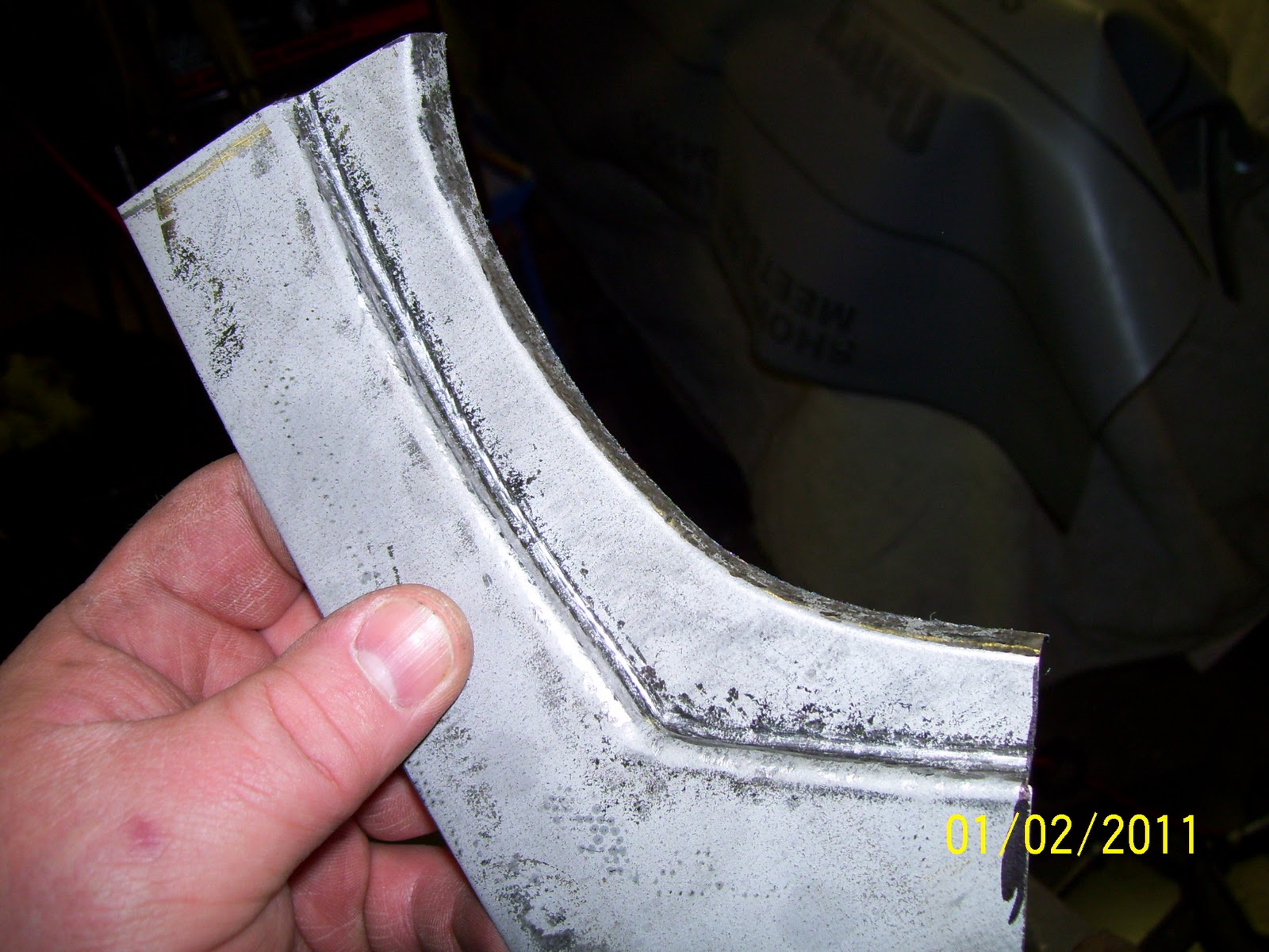
| And there it is! A completed, hand-made patch panel ready to weld in place. |
 |
| If you look closely, you can see the scribe lines in the machinist dye where the rotten part needs to be cut away. Also note the flash rust areas that came up immediately when the spray dye was applied. I should have used brush-on dye instead. |
 |
| Before cutting the bad section out, I drilled two holes in the corners of the repair area to allow the abrasive wheel to complete the cuts without snarfing up the corners of the repair. First the top..... |
 |
| Then the bottom. |
 |
| With the rotten section cut out I was able to fit the patch to the kick panel quite closely. A little massaging of the patch and panel edges and the patch was clamped in place for welding. |
 |
| The patch was tacked in place and everything was checked once more to make sure it was in order before welding. Looks good! |
 |
| After a few tense moments, the patch is fully welded in place. |
 |
| With welds ground smooth and the surfaces brushed clean, the patched area looks quite serviceable, albeit not perfect. However, once prepped and painted, it will be completely invisible. |


Sven, I don't know what to say. I am completely blown away. You showcase some mad sheetmetal skills here my friend. OUTSTANDING!
ReplyDeleteThank you very much Alex! I appreciate your kindness.
ReplyDeleteAmazing way of the use of tools. When you broke out the mason chisel I was blown away just like Alex said. Great work and thanks for an idea on a problem I have!
ReplyDeleteI truly am happy to hear that something on my blog may prove useful to more than me. Keep up the good work guys and thanks for the encouragement!
ReplyDeleteI have been watching your blog and it was a pleasure to see you identify the problem and find a solution. I can't wait to see the finished Mustang. Keep up the good work!
ReplyDeleteExcellent repair there Sven... and again, terrific detail for all to see on how you approached and ovecame the issue.
ReplyDeleteJeryjon and Mike,
ReplyDeleteThanks very much for the boost and I am really glad these sort of "documented dilemmas" are proving useful to more than just me! LOL!
Wow, that really is great work!
ReplyDeleteYou are quite amazing, look forward to reading more and seeing the final unveiling!
ReplyDeleteI really appreciate that! I invite you (and everyone else) to become a follower of my blog. There will be tons more to come!
ReplyDelete