Sunday, March 11, 2012

Tail Light Panel and Trunk Floor – Part 11: Tail Light Panel Install Complete

Today was a GOOD day!  When the fall and winter season began, I had a pretty tight plan on what I thought I could accomplish before the Spring and I am very happy to report, that it appears that plan will work to perfection.  With the installation of the rear tail light panel, I am happy to say the major structural repairs to my car are complete.  I still have to complete the welding on the axle tunnel repair panel seams and get the new panels in primer, but at least I have the comfort in knowing the car is structurally sound once again.
Several weeks ago, my Dad and I raided my local NPD for a truckload (literally) of sheet metal that included a new tail light panel and trunk lock support bracket to complete my panel replacement at the rear of the car.  The tail light panel was a very nicely detailed stamping that fit the car quite well.  The trunk latch support on the other hand was less so and required a bit more tweaking to get in order.  Nothing major, just tweaking.
I started the installation by carefully centering and squaring the new trunk lock support on the inboard tail light panel.  I have seen a lot of variability in the location of these brackets over the years, but it is critical that this be well centered so that the trunk lock mechanism works smoothly and the fuel filler tube passes through without interference, so take your time and get this right.
With the lock support welded in, I was finally to the point I could start the final fit of the tail light panel.  The first thing I did was to establish the center of the rear trunk floor aperture and I did the same on the tail light panel lower interior flange.  I reasoned that if my preparatory work was accurate, these two lines would line up when the panel was in its optimum position.  This idea was a good one as alignment was easily verified with these reference points and positional repeatability was spot-on.
The first observation during the panel mock-up was that both quarter panel end cap flanges overlapped the upper raised panel bead on the tail light panel significantly.  This prevented the panel from seating on its end-flanges properly and generally looked unfinished.  So out came my trusty paint pen and straight edge and I marked the appropriate trim lines that would allow the panels to mate correctly.
With the end cap flanges trimmed, the panel fit amazingly well.  This allowed me to install Clecos in the four corners with confidence and clamp the flanges with welding clamps such that I could accurately locate the spot weld locations around the panel.  Once this operation was complete, I punched the required plug weld holes with my pneumatic punch and drilled the few remaining holes I couldn’t reach with the punch.  After a little deburring of the drilled holes, I fit the panel once again to verify everything was looking flight-ready.
The actual welding of the panel went smooth and without drama.  I started by locking down the corners where I had the clamps located and then moved around the panel, welding the spots between the clamps to ensure tight flange fit and little distortion.  After about an hour of welding and cooling each spot with air, the panel was fully installed and the chassis was solid once again.
I still need to weld in the bumper brackets, complete the axle tunnel welds, trim the drip edge at the front edge of the trunk floor, and prime the whole area, but those are small jobs that will be made much easier now that the car can be rolled over in the rotisserie again without concern for the integrity of the structure.  It was a very good day…….

The tail light panel; installation was preceded by having to align and weld in the trunk latch support to the panel.  This is much easier than trying to do this with the panel tacked into the car.

The first mock-up of the tail light panel shows the fit was remarkably good.  Only slight tweaks would be required to get it right.

I was amazed at the fit at the lower rear of the trunk floor in the unclamped state!  Couldn't ask for better.

Here, you can see the overlap of the end cap over the upper character bead on the tail light panel.  This wouldn't allow the panel to register fully against the end cap flange as evidenced by the gap in the upper corner of the end cap.  This will need to be trimmed and hand fit to work properly.

Exact same overlap condition existed on the right side of the tail light panel as well.

Using my trusty paint marker and a straight edge, I marked the end cap flange where I needed to trim it back to fit.

Here is the right side marked for trimming as well.

With the tail light panel removed it is much easier to see the extent of trimming required on the left end cap flange.

The right side end cap flange required just a little bit more trimming for proper fit.

Left side end cap is trimmed and ready to go!

Right side end cap also ready.

Now you can see how consistent the panel bead reveal is and the corner fit is much tighter.

Right side fit is also very nice.

After marking and punching the spot weld holes in the end cap flanges, I clamped the tail light panel in place and located it with Clecos

This is a slightly better shot of how I mark the weld location on the tail light panel flange for sanding later.

Welded!  This panel went in like butter and the flange fits were superb!

Right side shot of the panel welded into place.

A shot along the bottom edge of the tail light panel flange.

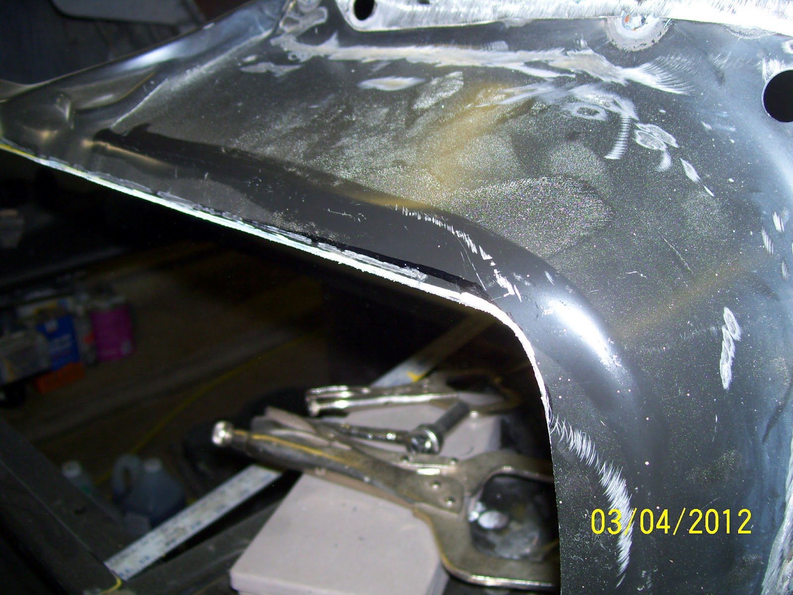
Left side end cap area after a bit of metal finishing.

Right side end cap area after metal finishing.

Only a spot of high-build primer will be required to smooth this flange area.

After welding, the trunk floor to tail light panel interface still looks tight and right.

Another shot down the lower flange to show how straight everything turned out.

I just HAD to throw the end caps, trunk lid and some old tail light bezels in place to see how it looked!  Awesome!

It's been a LONG time since this 'ol girl looked so "complete" in the posterior.  A good day indeed!

Thursday, March 8, 2012

Hydraulic Clutch Master Cylinder Work

I have to begin by apologizing for the poor photographic account of this latest work as I had a minor camera glitch (actually operator error) that prevented me from capturing some early “set-up” and template making shots, but hopefully you’ll get the idea.

A long time ago, I decided that a mechanical clutch linkage was not going to fulfill the design intent I had in mind for my car.  The factory 70 Mustang clutch “Z-Bar” linkage intrudes heavily on the under hood space where you’d rather put headers and generally clutters up that corner of the engine bay.  After a lot of research, I decided I liked the look of the latest generation of hydraulic clutch kits from Modern Driveline.

Since my plan is to run a “Z-spec” T5 transmission and late model Fox body Mustang bell housing, clutch, 157-tooth flywheel and mini-starter, I wanted something that was simple and easy to install.  Generally speaking, I seem to have gotten that in this kit.
Knowing ahead of time that Mustang firewalls are all over the map as far as hole stamping locations are concerned, I was prepared to have to do some tweaking to the parts to make them fit as I had intended.  As such, when I began to trial fit the clutch master cylinder mounting flange to the inboard side of the firewall, I knew right away what measures would be required to make it fit properly.  So out came the template paper and off I went.

The flange, as it is shipped, is a symmetrical shape, but I quickly learned that to fit my specific car, I would need to trim and contour the right side edge of the mounting flange to work with the stamping contours of the firewall.  My mission was to do nothing more than drill the required mounting holes and as luck would have it, I was able to meet that goal with very careful positioning of the flange.
With the mounting flange modified and fitting the firewall well, I moved to the outboard side of the firewall and with the help of my Dad, was able to secure the mount into place to verify the fit of the master cylinder and the original booster.  Fortunately, the Wilwood master cylinder bolted right up to the base adapter and the factory booster popped right into place with absolutely no interference whatsoever.  The fit is snug, but extremely clean and tidy.  Coupled with the rack and pinion steering and a restored booster, this area of the engine bay should be very clean and functional with a look that defies the observer to recognize it as anything but stock.  So far……I love it!

Here is the modified Modern Driveline hydraulic clutch master cylinder mount in place.  The mount comes as a symmetrically profiled part, but I was pretty sure that wasn't going to work out of the box on my car.  I was right, but the correction was easy with an accurate template and a few minutes with the grinder.

Here is the firewall mount for the master cylinder.  The original clutch rod hole is intact and unmodified although the new master cylinder hole location is to the far right of the original (larger) clutch rod hole in this shot.

Here is the Wilwood master cylinder mocked up on the new mount.  Cleeeeeeeeean!

Here is the view of the new master cylinder and pushrod from the "business end".

The clearance to the original vacuum booster is quite adequate even though this shot makes it look rather close.

This view give a much better idea of how much clearance there actually is.  I think I'm going to like this!

Monday, February 20, 2012

Steering Column Work: Powder Coating & Shrink Tubing Install Trick

One of my regular avocations is custom powder coating.  I keep quite busy doing mainly custom motorcycle, bicycle and hot rod work and on occasion, I get to do some of my own parts as well.  Recently, I was doing a poop-load of black powder work in the exact color I have chosen to do several critical pieces of my Boss in.  This allowed me the opportunity to coat my steering column shell and dash bracket and to show a little trick I developed to duplicate the factory shrink tubing used to encase the lower collapsible section of the Mustang steering column.

I started by stripping all of the factory finish off of the column and bracket and passing them through my blast cabinet to remove the rust scale that had accumulated over the years.  Then I applied a urethane matte black powder coating to both parts to ensure years of trouble-free service and great appearance.  And now for the “trick”:
Almost everyone I talked to that has ever restored a Mustang has stumbled a bit when it came to restoring the shrink tube encasement at the bottom of the steering column.  I’ve seen lots of Mustangs that have nasty looking original shrink tube sleeve still intact on otherwise nicely restored columns or, on the flip side, the owner has cut off the offending tube and left it off complete because they could not duplicate the process.

I was part of the “unlucky” group where this shrink tubing was concerns in that all manner of rodent had chewed up my original shrink tube jacket on my original column.  After months of scouring the internet for hints on how to repair this area, I came up with almost nothing helpful.  So, I started to think about a way I could recreate this detail on my own, and what I came up with worked better than I expected.  So much so, that I thought it only prudent to pass it along here.
In my research, I came across some very large heat shrink tubing for large industrial electrical cable that I thought might do the job.  Unfortunately, most of these products didn’t have the proper shrink factor I would need to do the job.  Then I stumbled upon some high shrink factor tube that would fit the bill from a company called Parts Express.  The shrink tube I found is referred to as 3” high-shrink rate tube.  It shrinks with a diametric factor of 2:1 and a linear factor of 1.07:1.  The stuff is a bit expensive, but I decided to order enough material to do a few columns just in case I blew it on the first try.

I measure my original shrink tube that I cut off my column and determined the finished length I required.  After taking the shrink factors into consideration, I cut a length of shrink tube  and slipped it over the collapsible section of my refinished column tube and began gently warming it with my heat gun while rolling the column tube slowly, making sure to evenly shrink the tubing from end to end.  After a few short minutes, I had a nicely finished detail that (I think anyway) replicates the original shrink tube nicely.  Hope this might be useful!
Steering column tube and dash bracket in the powder booth and ready to coat.

A nice coat of urethane matte black powder looks really nice.

My original shrink tube jacket was chewed up by rodents after years in storage and generally looked like crap.  Believe it or not, this is the "good" side.  There is very little information available on how to duplicate this detail so I set about figuring this out.

I found some industrial, high-shrink rate tubing material and started to experiment.  I found the 2:1 diametric shrink rate was spot on and determined the linear shrink rate was only 1.07:1.  This proved to be a perfect match for the requirements of this job.

I measured off a 10.75" section of shrink tube and cut it squarely with my razor knife.

Here is the new shrink tube placed on the collapsible column section before shrinking.  The nasty original is shown next to it for reference.

Being a single fella, I can get away with a lot of restoration "stuff" in my kitchen that many "spoken for" fellas don't get to do!  Using my heat gun on low heat, I started to slowly shrink the tubing by heating along the entire shrink tube sleeve by rotating the tube and heating it along it's length.  In this shot you can see the tube has just started to shrink around the ribs of the column tube.

about 30 seconds later, and the tube is pretty well secure on the column an shrinking nicely.  Note the ends are not quite tight to the column yet.

Almost there.  I have been heating the shrink tube about 90 seconds at this point.

And there it is.  The tubing has shrunk to its maximum and the ends are nice and snug against the column tube.

Compared to the original shrink tube jacket, I think this will work just fine.

With the dash bracket in place, this restoration detail really sets off the column well.

Tail Light Panel and Trunk Floor – Part 10: Front Trunk Floor Install

Quite a while ago, I posted a blog entry railing on the total lack of quality of every single front trunk floor patch available today along with the work I had to do to get the panel to fit correctly.  At long last, I have reached the point where the last heavily rusted panel I had could now be replaced.  And MAN does it feel good!

This repair will feature a panel joint repair that I use rarely, but works very well in certain situations.  The joint is called a lap joint and it is very useful on panels where the span is long and there is no feature(s) in the panel to add strength and resist warping.  In my case, the entire width of the front trunk floor repair was of this configuration and determined I could not adequately butt weld the entire joint with hope of success.
I began by trimming the floor repair panel to the basic dimensions I required to make the repair.  I had marked the location of the repair several months ago with a white paint pen to remind me of where I wanted to join the repair panel to the parent metal when the time came to make the repair.  By transferring a few dimensions to my repair panel, I was able to get the seam located where I wanted it.  I added ½” to the dimensions so I had enough material on the repair panel to allow a flange to be created.

With the panel trimmed, I then used my pneumatic flanging tool to flange the entire top edge of the panel to allow the parent metal to neatly fit underneath the panel flange.  This creates a surface on the “finished” (a.k.a. bottom) side of the axle tunnel that can be made smooth and straight with minimal filler once all of the welding is complete.  Also, the lap joint it creates on the bottom is much easier to weld cleanly and without burn-through than a conventional butt weld joint.
Next, I used the repair panel as a marking template to locate the cut line for the parent metal ½” below the top edge of the repair panel flange.  Using my trusty screaming-wheel-of death (a.k.a. pneumatic cutoff wheel), I cut off the rust-damaged portion of the original front trunk floor and deburred the edges.

At this point, I spent a good bit of time carefully clamping the repair panel and parent metal to ensure the fit between the two was a good as I could make it.  Once I was satisfied with the fit, I locked the panel in place using my high-clamp-force Cleco fasteners.  Another check of each seam to verify fit and it was game time!
I wanted to be able to flatten the welds a bit over regular plug welding so I ran the heat and wire speed up just a tick on the MIG welder.  This game me a quick arc start and smooth metal deposition that I would not have been able to use with a butt weld.  This technique worked great and I stitched the panel in place quite quickly.  While I was there, I also welded up a number of spots along the top of the axle tunnel that I had marked several months ago.  Once the stitch welds were complete, I checked the fit from underneath and was pleased that the flange fit was good and warpage was minimal.  A little bit of hammer and dolly work had the parent metal flange seated tightly in the recess of the repair panel flange.  This edge is now ready for a fully seam weld from the underside to complete the installation.  This step will have to wait until the tail light panel is installed and the car can be rolled over in the rotisserie without concern for the body inadvertently shifting without a complete structure to support it.  In the meantime, the panel won’t be going anywhere.

The last area that required repair in the front trunk area is the aperture where the factory cut out the axle tunnel for the staggered shock mount to pass through.  In an earlier post, I showed how crudely the factory had cut this opening using a torch and apparently not much skill or precision.  Naturally, this area would require a bit of clean-up before I could make a patch to repair this area, so I traced the opening with trim lines that would allow me to square the hole before going any further with patch fabrication.  With the hole trimmed to the lines, I was able to trace the hole on a piece of cardboard.  I added a ½” border flange around the hole traced on the pattern and transferred this shape to piece of .025” steel patch material and cut the patch on my band saw.
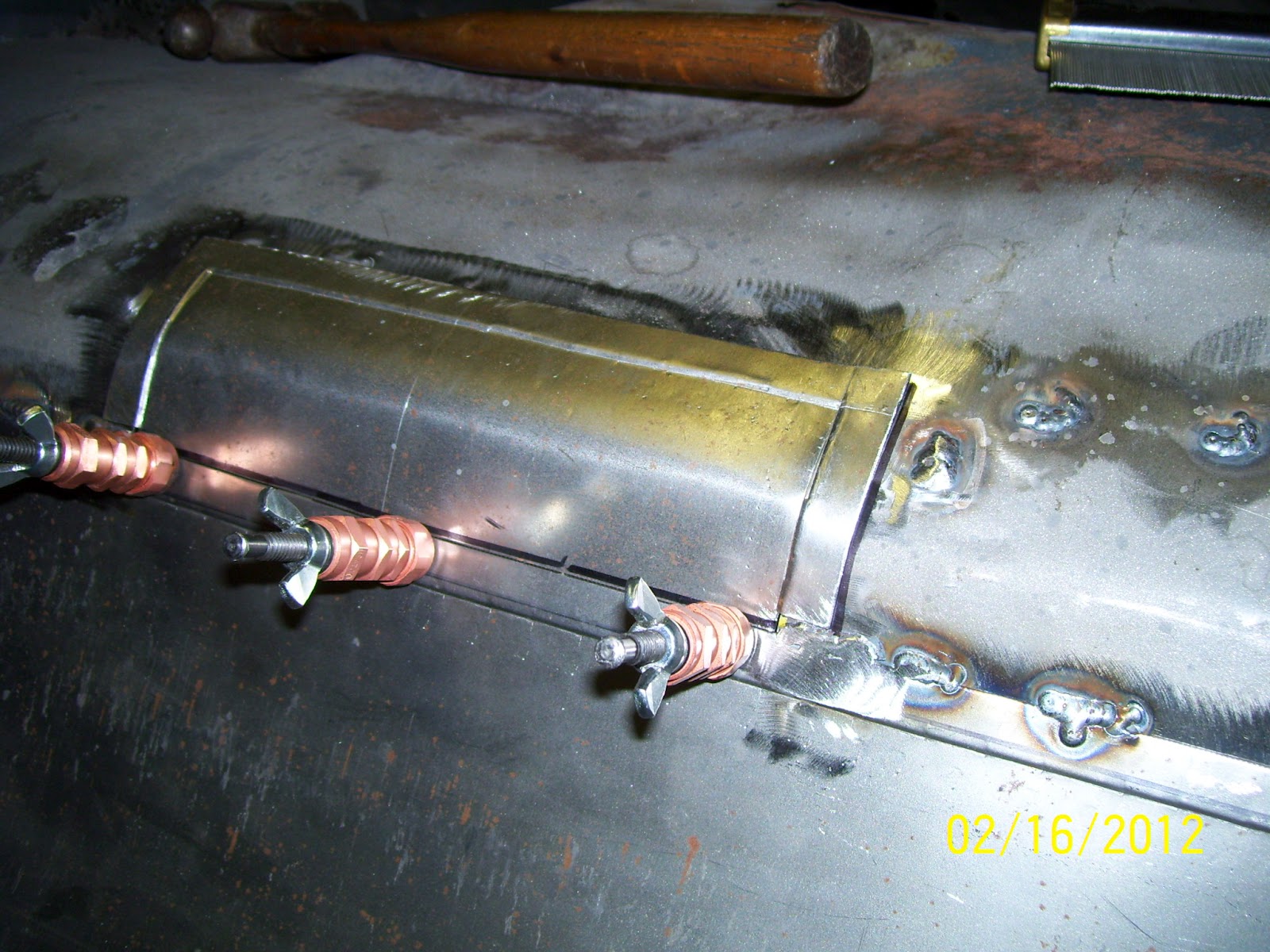
Moving to my flanging tool, I once again flanged the patch along three of the four sides, leaving the lower edge of the patch flat to allow it to tuck underneath the previously installed trunk floor patch.  Next, I took my contour gage and made patterns of each end of the patch are so I could carefully form the patch to match the shape of the axle tunnel.  When I had the shape correct, I secured the patch with Clecos and tacked/stitched the patch in place in the same manner I did with the larger trunk floor panel.  Once all the top-side welding was complete, I smoothed up the welds with my angle grinder and some 60-grit disks and this phase of the trunk floor repair was complete.

From the bottom of the axle tunnel, the repair is quite smooth, and after a little bit of body work and filling, it should be virtually undetectable.  There’s a good bit of welding left to do to finish the joint, but that will have to wait until the tail light panel is installed so I can once again roll the car over on the rotisserie.
My pneumatic flanging tool made forming this step flange along the edge of the front trunk floor repair panel a quick and tidy job.

After trimming the repair panel to the length I needed and flanging the leading (top) edge, I marked the parent metal with my yellow paint marker to establish a reference line to work from so I could mark the cut line on the parent metal.

From the reference line I marked in the previous step, I dropped down 1/2" and marked the cut line of the original metal.

My original white sketch line can be seen right between the upper reference line an the lower cut line.  Also in this shot, you can see the locations of the small areas I need to weld up (shown as white squares).

Using my cutoff wheel, I carefully cut the rusty lower section off the car, leaving a clean edge, ready for the new panel to be clamped to.

The repair panel was then secured using high-clamp-force Cleco fasteners.

Here's a close-up of the left side of the trunk repair panel clamped into place.

A quick check from underneath shows the joint edge is nice and flat and ready to be tacked/stitched in place.

A few minutes later, and the panel is securely stitched into place about every 2.5 to 3" along each edge.  Notice the minimal heat affected zone around each weld.

Here's a look at the right side of the front trunk floor repair after tacking in.

Another shot from underneath shows a clean, straight edge that is ready for complete welding.

The remaining issue in this area was the hole the factory cut for the staggered shock mount to pass through.  This hole was quite nasty, so I decided to trim up the edges so I could create a nice clean aperture to fit a patch to.

Here, I have cleaned up the hole into something i can work with.

I made a simple cardboard pattern by tracing around the hole and adding the requisite 1/2" flange allowance around the perimeter.

After cutting out the patch blank on my band saw, I flanged the side and top edges of the patch.  This would allow the lower edge to slip behind the trunk floor repair panel to match the parent metal flange.

I used some simple cardboard templates I made for each end of the repair area to duplicate the shape of the floor at each end.  This allowed me to for the patch to precisely fit the hole. 

Here you can see the tight fit against the original Axle tunnel I needed to ensure the patch panel fit as required.  I clamped the lower edge of the patch with Clecos to help make sure the patch was located precisely while fitting.

Here is the view of the finished patch panel from under the car.  You can see how nicely the patch integrates into the trunk floor repair panel and the parent metal area above it.  These flange joints will make fully welding in the repairs much easier by reducing the tendency to burn through significantly.  Also, the warpage is considerably less with this style of repair joint.

Clamped into place, the patch is ready to be tacked in.

The patch panel has now been fully tacked into place and looks excellent.  I also welded up the spots along the top of the tunnel as well.

From underneath, you can see the repairs are smooth and the seams quite straight.  I will fully weld each seam after the rear tail light panel is in place so I don't have to worry about the body shifting on the rotisserie.

Done!  A few minutes with the angle grinder and the top side of this repair is complete.