Sunday, April 3, 2011

Toe board patches & rear torque box covers

As spring tries desperately to show its mug here in not-so-sunny Michigan, I have managed to make the best of the comfort and security of my shop to make significant headway on the Boss.  When I left off, I had managed to sand blast the areas of the floor pan area that I would be working on over the next several weeks in preparation for the installation of a new, one-piece floor pan.  With nice, clean metal to work with, I set off on a mission to replace the damaged metal in both front toe boards where the ravages of rust left their distinctive mark along with repairs to each of the rear torque boxes which were damaged as well.
Before the sand blasting, I had already cut and fit the toe board patches, so I was confident that I had good pieces to work with when it came time to weld.  However, the removal of the old floor left several spot weld cutter divots in the frame rail flanges and along the floor pan flange areas that I needed to weld up and smooth before going any further.  This involved a good solid evening of welding and subsequent grinding to get everything in shape.  Also, I discovered two more stress cracks above the rear driveshaft tunnel that required welding as well.  However, with everything welded up and ground smooth, I was happy to have nice flat flanges, ready for a new floor.
Before moving on to some strategic application of Zero Rust paint, I sprayed everything down with phosphoric acid to prep and protect the bare metal surfaces.  After letting this dry overnight, I scrubbed everything with mineral spirits and a scotch bright pad to remove any excess deposits (especially on the galvanized metal) and let that dry thoroughly.  This left a nicely phosphatized surface that was ready for a thinned coat of Zero Rust in the hidden areas below the toe boards as well as the rear torque box enclosures.
Since I had already fitted the patches to the toe boards, I started by locating and drilling each plug weld that would be required in each patch.  Because the passenger side patch was so small and required so few plug welds, I could effectively clamp the patch with locking pliers and welding clamps without the need for clecos.  As such, this patch went in quite quickly.  As another testament to the Lincoln 180C wire feed welder, the weld penetration on this very thin sheet metal was remarkably good and I only needed a little bit of “touch-up” on the back side to make me confident that the patch was welded securely.  After a little bit of clean-up grinding, I rolled the bottom edge to duplicate the features of the original panel and to add some strength to the free edge.
The driver side toe board patch required quite a bit more effort to install due to its size and complexity compared to the passenger side.  With a combination of clecos, welding clamps and locking pliers, I secured the panel in place and began by tacking the edges of the patch in place to lock everything down without fear of disturbing the precise fit between the panel and the main structure.  From there, I systematically drilled plug weld holes with my spot weld cutter at each cleco location a replaced the clecos with plug welds as I moved across the patch.  This technique pulled the patch down nice and tight against the underlying structure and allowed the remainder of welding to proceed without fear of the patch moving around.
With both patches fully welded in, I rolled the lower edge of the driver side patch and finished them up by grinding each seam flush on the inside and outside.  Once I have the floor in, I will skim the seam areas with a thin coat of filler to smooth the entire area, making the repairs completely invisible.
Next on the agenda was to complete the repairs to the rear torque boxes.  First I straightened the lower surfaces of each torque box using the same technique I used to straighten the lower surfaces of the front frame rails a few episodes back.  With the panel beating done, I fit each torque box cover and scribed where each one required trimming.  Using my trusty pneumatic metal-eating-wheel-of-death, I cut off the extra material I didn’t need and drilled the plug weld holes along each flange.  The nice, wide flanges of these panels make drilling the plug weld holes quite easy.
With both torque box covers trimmed, drilled and fit, it was time to clamp them in place and weld ‘em in!  Here again, the locking pliers, and welding clamps are critical to getting these complex little panels to fit well on all flanges.  In fact, other than being a bit short on the inboard flange edges, these patch panels from NPD fit quite well and require very little massaging to work well.  Once clamped securely in place, I simply walked around the panel with plug welds, moving the clamping pliers and welding clamps as I went, until everything was solid.  As with the other patches, I ground the welds down smooth with my 2” angle grinder and prepared to coat the new patches with phosphoric acid to protect the new metal.
Next on the agenda will be to fabricate the patch panel to repair the driver side rear floor transition panel that was devastated by rust.  I have been studying this closely and might just have a sneaky, underhanded, absolutely unauthorized trick up my sleeve to pull this repair off………..maybe.
I drilled several spot welds a bit too deep with the spot weld cutter and didn't like the divots left behind.  So, I decided to weld up each one of them around the floor area to make sure I would have good solid flanges to work with.

Here are several repairs made to the rear frame rails and floor flanges.

While I was inspecting this area after sandblasting, I discovered two more stress cracks (four total) at the rear tunnel area that required welding.

Weld divots and stress cracks welded and ground smooth at the rear floor area.

Rear frame rails looked very nice once the welds were smoothed.

Although almost whitewashed in this picture, the actual surface of the phosphatized surfaces is not nearly this spectacular.

Here are the flange areas at the rear after phosphoric acid treatment and scrubbing with mineral spirits.

The torque boxes are galvanized and take on a heavy white/grey patina after phos.

Another look at the galvanized rear torque box areas after phos.

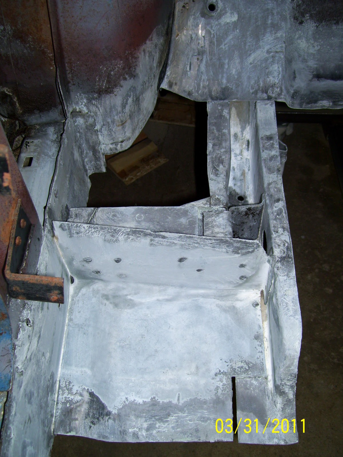
As much as I hate brushing on Zero Rust paint, it was the best way to protect the hidden areas under the toe board patches.  Here is the passenger side.

Here is the driver side toe board area coated with Zero Rust.

I coated the inside of both rear torque boxes with Zero Rust as well.

With the passenger toe board patch pre-fit, I just added a few plug weld holes and clamped it in place.

I tacked the patch in place and followed up by welding up the plug weld holes.

The panel was fully welded around the perimeter using short weld "stitches" around the seam.

Weld penetration with my new welder is excellent!  I love this machine!

The free edge of each toe board is slightly rolled to match the look of the original panel and add strength.

The driver toe board patch was clamped and cleco'd in place to secure it precisely.

I started by tacking it completely around the gap to ensure the fit was locked down.


Then I systematically replaced the clecos with plug weld holes drilled with my spot weld cutter.  Then I simply walked around the panel welding up the plug welds at each location.


Here's the driver side patch from underneath after grinding.

And here's the passenger side.......
Passenger toe board from the top.
Driver side toe board from the top.

The torque box covers were first clamped into place and scribed for trimming and marked for plug weld locations.


Rear torque box cover after trimming and drilling.  We're ready to weld!


To keep everything in place for welding, I use many clamping pliers and welding clamps to keep the fit tight.

Here is the passenger torque box cover welded in.

And here's the driver side torque box cover welded in.


With the welds ground smooth, the torque box covers are ready for the next step.


With a coating of phosphoric acid, the metal will be protected until I can get the floor pan installed and primed.

Driver side toe board after phosphoric acid treatment.

Finished passenger rear torque box  after phos.

Finished driver side rear torque box after phos.

Monday, March 21, 2011

Floor area sand blasting & a little teaser

I have come to realize one thing after this weekend:  God must love Boss 302s!  How do I know this?  Because he was kind enough to hold off raining all over my nearly-nekid  car until Dad and I managed to get her safely inside the shop, and all our blasting sand recovered and put away.  Yep…..after two solid days of slinging sand all over creation, I was rewarded with a host of clean metal that was refreshingly solid and surprisingly lacking in the heavy rust damage that was present in so many areas of this car.  I am very happy to say that I have reached a point where the major rust damage finally has been removed and getting the new floor welded into the car will have the car about 65-70% structurally complete.  Still a lot of complex work to go before “normal” restoration work begins, but pretty significant progress nonetheless.
At this point, the car is ready for me to treat the bare surfaces with phosphoric acid, and start welding in the three major patches required before the floor is installed.  This alone will take a few weeks to complete as I still have to fabricate the rear floor transition patch.  In the meantime, I will repair the toe boards and clean up some spot weld cutter divots in the front sheet metal flanges.  From there, I will coat the inner rockers and firewall area with Zero Rust for protection and move to the rear floor sections needing repair and straightening.  Again, lots of work, but great to know that progress is finally starting to show.
For pure entertainment, I also mocked up the Heidt’s four-link forward bracket assembly.  This is the major structure added to the car that functions as the forward mounts for the upper and lower trailing arms.  While the kit is marketed (and many magazine articles show it) as a “bolt-in” kit, I find this is not likely to be the case.  The subtle differences in the 69-70 chassis dictate some slight modifications will be required to make the brackets fit perfectly.  In addition, some gaps exist where the bracket saddles the frame rail that are considered “normal”, but that ain’t so around here.  Since I plan to weld these structures into my car, I insist that they fit well, while gaps like this may be fine for bolted installations, it won’t be tolerated for a welded installation.  So…..more fab work ahead...........as usual.  Did I mention I think God loves Boss 302s?


Here's the car ready for a day of blasting. 

In the pre-blast inspection, I found two more stress cracks in the chassis.  This one is directly beside the axle snubber pad at the rear of the driveshaft tunnel.


Passenger side lower torque box and spring mount area looks very nice after blasting.  The water-spotted look of the torque box is actually the patina the galvanized metal takes after blasting.


Trans cross member and passenger frame rail cleaned up quite nicely too.


Driver side inner frame rail and cross member also looks good.  Note the galvanized material used in the cross member.


More galvanized metal.  Here you can see the distinct difference in finish of the blasted galvanized metal of the frame rail and lower torque box versus the plain steel of the leaf spring mount in the center of the image.


Passenger side of the axle tunnel looks surprisingly solid.  A little clean-up in this area will work wonders.


Here is the driver side axle tunnel.  As you can see, I didn't bother blasting the section of the floor transition I plan to remove and replace with new metal.  No need to waste the sand......


Driver side inner torque box is excellent!


Inner frame rails cleaned up very well.  Spot weld cutter divots will be welded up and ground smooth before the floor goes in.


The firewall also cleaned up quite well.  Still needs a bit of wire wheel work to get everything clean, but that part is comparatively easy.


Trans cross member is really very solid.  Again, a galvanized part.


I couldn't resist mocking up the Heidt's frame mounts.  Here's how they tuck into the original leaf spring pockets.


While this 3/16" gap between the frame rail and frame bracket may be considered "normal" for bolted-in Heidt's four-link conversions, it is unacceptable to me.  This will be filled with a steel "shim" welded to the frame a base and this bracket will then be welded to it and the frame as a solid assembly.


On 69-70 mustangs, the inner wheel houses are actually slightly farther inboard than in earlier models.  This creates a slight interference to the Heidt's frame bracket.  A slight bit of massaging of the metal will solve this problem quite quickly.


Another look at the gap that I will fill before installation.


Sunday, March 13, 2011

Driver toe board patch fab and rear floor removal completed

The weekend proved to be quite productive after a pretty slow last few weeks.  When I left off, I had yet to remove the damaged toe board section from the driver side.  I felt a little more thought was required before I cut out the section and the end result was a slight change in how I would cut the inboard side.  Once I settled on the method, I marked the general shape on the existing toe board with soapstone and set about making the toe board patch mirror the shape exactly.  I have learned it is best to make the patch panel first, and then trace the outline on the original part so you can precisely match the cut to the panel that will be welded in.  With this technique applied, I marked the section to be cut, drilled the spot welds that were involved and carefully cut just inside the cut lines with my panel cutter (a.k.a. the wheel of death).  The whole process took about 30 minutes and as luck would have it, the panel fit perfectly.  Now that both toe board patches are fabricated and the rotted metal cut out, I set them aside until I can sandblast the areas for proper preparation for welding.
Next on the agenda was to remove the remnants of the floor flanges along the rocker boxes and then move on to removing the floor sections that remained at the rear along with the upper torque box covers.  Fortunately, the rocker flanges came out without much fuss, leaving the majority of the weekend to be dedicated to removing the rear floor sections.
This rear floor area of a Mustang can be quite tedious to remove because there is a high concentration of spot welds in a relatively small area and the floor flanges that mate to the inner wheel houses actually turn down under the car where the rest of the floor flanges turn up toward the inside of the car.  I had my hands full trying to locate each spot weld given so much of the metal was badly rusted making the spot welds almost impossible to see.  However, with a little patience and a nice variety of tools at hand, the final section of the old, rusted floor hit the floor with little protest.
I have to admit I was very nervous to uncover the rear subframe and torque box cavities as I was sure they would be destroyed by rust.  Well, I WAS WRONG!  What I discovered in both locations was clean, solid metal that would require a little massaging to get straight, but no replacement!  Luck just doesn’t describe it…….
The joy at this discovery was tempered somewhat by two “downers”.  The first I somewhat expected, but was disappointed at the severity.  Specifically, the driver side axle tunnel transition area where the floor meets the axle tunnel was much more heavily damaged by rust than I had suspected.  The other was relatively minor stress cracks at the rear drive shaft tunnel area.  Yet another indication of the abuse this car endured in its earlier life.
I’ll now set off to make a patch panel for the damaged axle tunnel transition and get it ready to weld in and repair the stress cracks at the rear of the tunnel.  Somewhere in there I am keeping my finger on the trigger of the sandblast gun with an eye on the weather………COME ON SPRING!
Removing the rear floor sections is tedious.  Lots of spot welds in a small area and some rather difficult to get to with a cutter.  Also, I was not confident I would have much to work with under that torque box cover with all of the rust in the floor and the perforations in the cover itself.  Was I wrong about that!
Other than light surface rust, the underlying metal in the passenger rear floor area was excellent.
The driver torque box cover was the better of the two, yet I still wasn't sure what I would find underneath.  To my surprise and delight, the torque box was pristine and had almost no rust evident at all!  The white powdery surface is actually from the galvanized metal itself and will clean up nicely with a light sand blasting.  Both torque boxes will get coated in Zero Rust paint before reassembly.
Another surprise was the equally good condition of the driver subframe. 

Bolstered by the good news on the driver side, I removed the torque box cover on the passenger side with fingers crossed.  I was astonished that it too showed to be in equally good shape!

And the same for the passenger subframe too!
My enthusiasm was tempered a bit by the more extensive damage to the flange just at the transition to the rear axle tunnel.  Quite an extensive patch will have to be fabricated to repair this section of the floor pan.

My final disappointing discovery was two rather significant stress cracks at the top corners of the driveshaft tunnel where it meets the axle tunnel.  I have discovered this is a common stress crack area in cars that were raced heavily or abused.  No surprise there......

From the floor to new Heidt’s – New stuff is the BEST!

Progress has been a little hard to come by lately, but I am happy to say, new stuff has been procured!  Over the past few weeks, I have managed to pick up a new floor, seat pans, rear torque box covers and the latest Heidt’s four-link coilover rear suspension system along with their subframe connectors.  Kinda feels like Christmas all over again!
As I mentioned in an earlier post, my car will ultimately ride on a full coilover suspension system.  The front suspension will be a very nice setup from a local company owned by a fellow named Shaun Burgess called Street or Track.  Shaun has developed one of the finest coilover front suspension systems available for the Mustang and it is also one that requires the least modification of any available (it’s practically a bolt-on affair).  Check it out here:   Street or Track Coilover Front Suspension Kit
The rear suspension is a bit more involved and I have chosen to go with the Heidt's Hot Rod Shop 4-Link Coilover Kit.  The Heidt’s stuff is extremely well made, easy to install and maintain and it works pretty darn well.  While they market the kit as a bolt-in, I will be welding the system into my car as I hate the “bolted-together” look and I want it to blend smoothly into the rest of the undercarriage.  Once the bottom of the car is sprayed with SEM bed liner coating, the whole setup should look as close to factory as you can hope for.  I’m excited!
I stopped off at NPD and picked up their top-of-the-line one-piece floor along with a pair of new seat pans and rear torque box covers.  The parts look quite nice and I am looking forward to being able to install them once the weather allows for some sand blasting.
When this load of stuff showed up, I was like a kid with anew bike!
There it is!  The 4-link rear suspension I have been waiting for!
......and a set of subframe connectors to go with it!
All unboxed and set out for inspection.  The Heidt's stuff is very nice.  All the steel parts are laser cut and look gorgeous straight out of the box.
The weld quality on every piece is second to none.  These frame brackets appear to be robotic MIG welded and are fantastic.
The 4-link brackets are TIG welded by hand and look very nice.
More very nice TIG welding on the lower coilover mounts.  Also, notice how smooth the laser-cut edges are on every part.  It's almost as if every edge was polished.