Pretty early on, I knew I wanted to get the body up in a rotisserie to effectively execute the restoration work on the bottom of the car. For as much work that has to happen below the belt line on a project like this, being able to flip the car over and work while standing up is a damn sight better than laying on your back on a cold, hard concrete garage floor.
I looked at many commercially available rotisseries on the market and didn't really like any of the units I found. Couple that with a price tag that I felt was outrageous, and it wasn't too hard to justify building my own.
After scouring the web for several weeks collecting ideas, I found I liked the unit built by a fellow who chronicled his build here:
http://www.harwoodperformance.bizland.com/1941buick/Editorial_20.htm
While not exactly right for what I wanted in a rotisserie, it certainly provided an excellent starting point and, with a few modifications, should work very well for my purposes. One of the major things I wanted to accomplish is to devise some way to allow the car to be rolled around on the floor when I needed it to yet make it simple to load in the rotisserie when required. Most designs I found use either hydraulic jack affairs on each end or a shop crane to lift each end of the car into position. I decided neither solution was particularly good, especially where small work spaces were involved. So I decided to design a front and rear dolly assembly that would bolt into the chassis in such a way as to keep the working height of the car optimum when rolling it around yet give me a stable means of using a common floor jack to lift the body high enough to load into the rotisserie without much hassle. With a little noodling, I came up with simple, easily detachable bolt-in dollys for the front and rear that fit the bill. The following are some shots of construction details throughout the build. In the next few weeks, the car will be mounted in the rotisserie and I will follow up with more pics. Stay tuned.
 |
| First frame welded together. |
 |
| Rear view. |
 |
| Both frames together and ready for top saddles, spindles tubes and casters |
 |
| A simple jig I made to mark the saddles for cutting. A little careful torch work and I was good to go. |
 |
| I clamped up the two frames with temporary jigs to make sure they were level to each other and fit the spindle tube. Once I was happy with the fit, I cut the spindle tube in half to make the final individual tubes for each frame. |
 |
| Here, we used a section of spindle material to keep each tube aligned while I tack welded them in place. |
 |
| The temporary jigs did a nice job keeping everything in place for final welding. |
 |
| With the spindle tubes welded in place, I drilled each one for a draw pin to keep the spindles locked in one of 8 positions. |
 |
| Here we have all four casters welded in place. |
 |
| A finished frame assembly ready to go. |
 |
| The major fabrication is over! |
 |
| Both t-brackets welded up. |
 |
| Details of the spindle head welded to the spindle. |
 |
| Frame bracket tube welded to it's slip collar. |
 |
| Test fitting the frame brackets, t-bracket and spindle assembly. |
 |
| This gives you an idea of what the whole assembly will look like when completed. |
 |
| Another view with the assembly roughly in place on the front of the car. |
 |
| Frame bracket bolted to the right front frame rail bumper bracket mounting holes. |
 |
| Trial fit with the frame brackets bolted in place. |
|
| Here is the completed front frame assembly with the new rad support in place. |
|
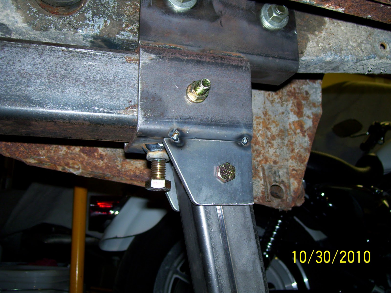
| Here is a shot of the right rear frame bracket and slip collar that bolts into the factory frame tie-down bracket bolt holes. The rear dolly bracket tabs have not yet been welded to the bracket slip tube in this photo. |
|
| The Mustang has a small bent flange at the very back of each rear frame tube that must be cleared by the body brackets to prevent damage. I used careful selection of material thicknesses to provide clearance for these flanges. |
|
| A view of the flange clearance from the rear of the car. |
|
The left side frame bracket and slip collar in place. |
|
| The rear frame assembly bolted in place. |
|
| Here is the mast of the front frame dolly caster. I used two u-bolts to secure the mast to the factory crossmember. |
|
| Here is the completed dolly bolted in place before the jacking point was installed. Notice the forward braces extend to plates bolted in the swaybar mounting locations on the frame for strength and stability. |
|
| Here is the jacking point in place on the mast. As I discovered later, this point is better placed on the back of the mast rather thn the front. I will make this modification over the winter so it's correct by spring. |
|
| Here's a better view of the whole front dolly assembly with the jacking point (see note above about jack point placement). With a three-point dolly (e.g., one caster in front and two rollers in back), the frame will always sit squarely and securely on the garage floor and no twist will be imparted into the frame from an uneven garage floor. |


That's a fine-looking tiss you've made there. Excellent work on your car too. Thanks for making this awesome detailed blog!
ReplyDeleteThanks! I appreciate the comments and really enjoy your blog and restoration too! Looks like we are covering much the same ground on both our cars!
ReplyDelete